Removing the Chassis Cover
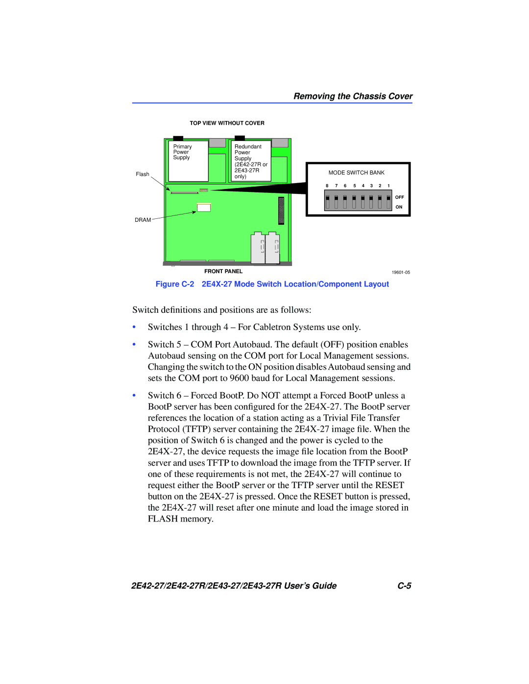
Flash
DRAM
TOP VIEW WITHOUT COVER
|
|
|
|
|
|
|
|
|
|
|
|
|
|
|
|
|
|
|
| Primary |
|
|
|
| Redundant |
|
|
| |||||||
|
| Power |
|
|
|
| Power |
|
|
| |||||||
|
| Supply |
|
|
|
| Supply |
|
|
| |||||||
|
|
|
|
|
|
|
|
|
|
|
|
|
| ||||
|
|
|
|
|
|
|
|
|
|
|
|
|
| ||||
|
|
|
|
|
|
|
|
|
|
| only) |
|
|
| |||
|
|
|
|
|
|
|
|
|
|
|
|
|
|
|
|
|
|
|
|
|
|
|
|
|
|
|
|
|
|
|
|
|
|
|
|
|
|
|
|
|
|
|
|
|
|
|
|
|
|
|
|
|
|
|
|
|
|
|
|
|
|
|
|
|
|
|
|
|
|
|
|
|
|
|
|
|
|
|
|
|
|
|
|
|
|
|
|
|
|
|
|
|
|
|
|
|
|
|
|
|
|
|
|
|
|
|
|
|
|
|
|
|
|
|
|
|
|
|
|
|
|
|
|
|
|
|
|
|
|
|
|
|
|
|
|
|
|
|
|
|
|
|
|
|
|
|
|
|
|
|
|
|
|
|
|
|
|
|
|
|
|
|
|
|
|
|
|
|
|
|
|
|
|
|
|
|
|
|
|
|
|
|
|
|
|
|
|
|
|
|
|
|
|
|
|
|
|
|
|
|
|
|
|
|
|
|
|
|
|
|
|
|
|
|
|
|
|
|
|
|
|
|
|
|
|
|
|
|
|
|
|
|
|
|
|
|
|
|
|
|
|
|
|
|
|
|
|
|
|
|
|
|
|
|
|
|
|
|
|
|
|
|
|
|
|
|
|
|
|
MODE SWITCH BANK
8 7 6 5 4 3 2 1
OFF
ON
FRONT PANEL |
Figure C-2 2E4X-27 Mode Switch Location/Component Layout
Switch definitions and positions are as follows:
•Switches 1 through 4 – For Cabletron Systems use only.
•Switch 5 – COM Port Autobaud. The default (OFF) position enables Autobaud sensing on the COM port for Local Management sessions. Changing the switch to the ON position disables Autobaud sensing and sets the COM port to 9600 baud for Local Management sessions.
•Switch 6 – Forced BootP. Do NOT attempt a Forced BootP unless a BootP server has been configured for the
|