Cabletron Systems 2E42-27, 2E43-27 manual Remove the screw from the rear standoff. Save the screw

Models: 2E42-27R 2E43-27R 2E42-27 2E43-27

1 164
Download 164 pages 19.47 Kb
Page 157
Image 157
2.Remove the screw from the rear standoff. Save the screw.

Installing Optional Fast Ethernet Interface Modules

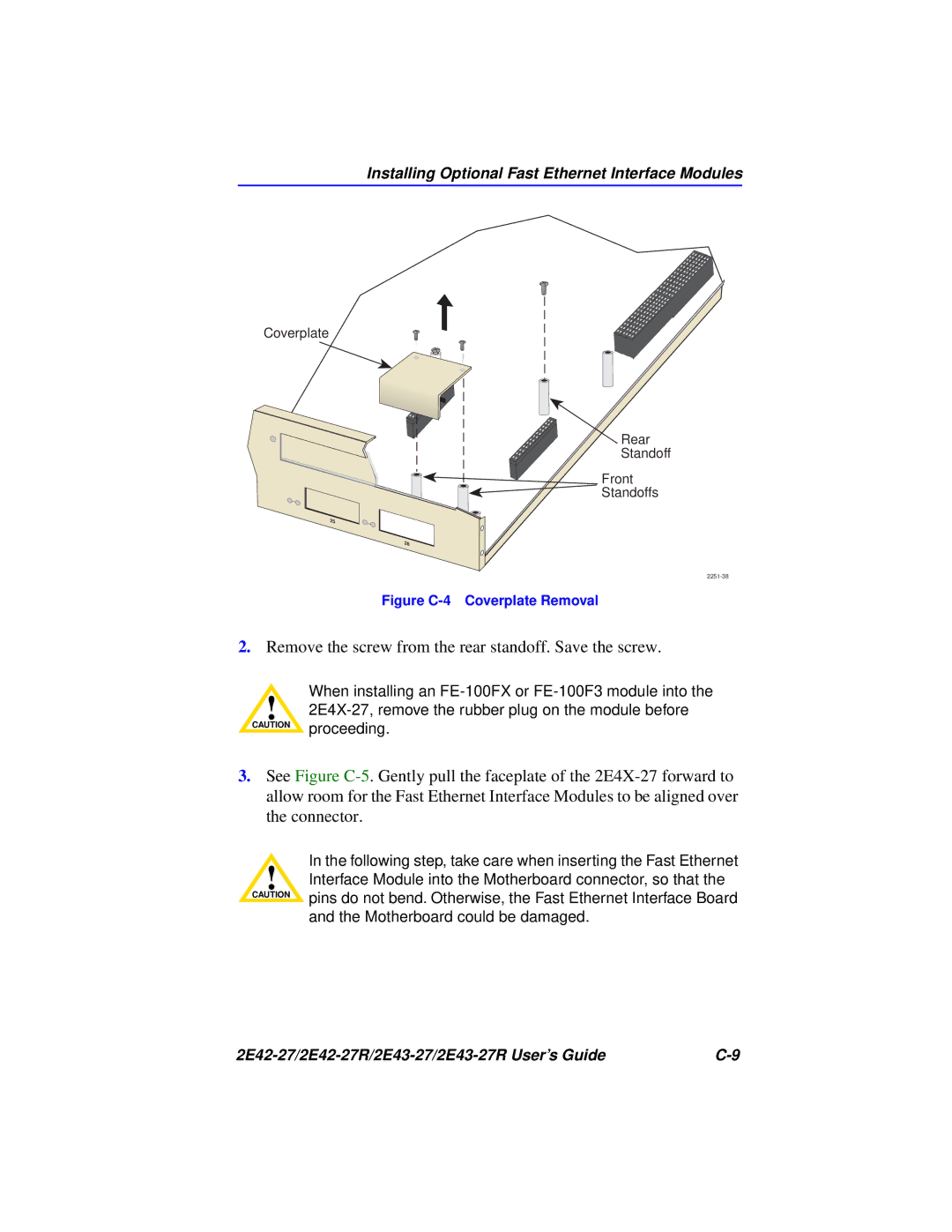
Coverplate

Rear

Standoff

Manual backgroundManual backgroundManual backgroundFront

Manual background Standoffs

2251-38

Figure C-4 Coverplate Removal

2.Remove the screw from the rear standoff. Save the screw.

When installing an FE-100FX or FE-100F3 module into the

!2E4X-27, remove the rubber plug on the module before CAUTION proceeding.

3.See Figure C-5. Gently pull the faceplate of the 2E4X-27 forward to allow room for the Fast Ethernet Interface Modules to be aligned over the connector.

In the following step, take care when inserting the Fast Ethernet

!Interface Module into the Motherboard connector, so that the

CAUTION

pins do not bend. Otherwise, the Fast Ethernet Interface Board


and the Motherboard could be damaged.

2E42-27/2E42-27R/2E43-27/2E43-27R User’s Guide

C-9

Page 157
Image 157
Cabletron Systems 2E43-27R, 2E42-27R manual Remove the screw from the rear standoff. Save the screw