Chapter 1: Introduction
Appendix A, Specifications, contains information on functionality and operating specifications, connector pinouts, environmental requirements, and physical properties.
Appendix B,
Appendix C, Optional Installations and Mode Switch Bank Settings, describes how to install optional Fast Ethernet Interface Modules and how to set the Mode Switch.
1.32E4X-27 FEATURES
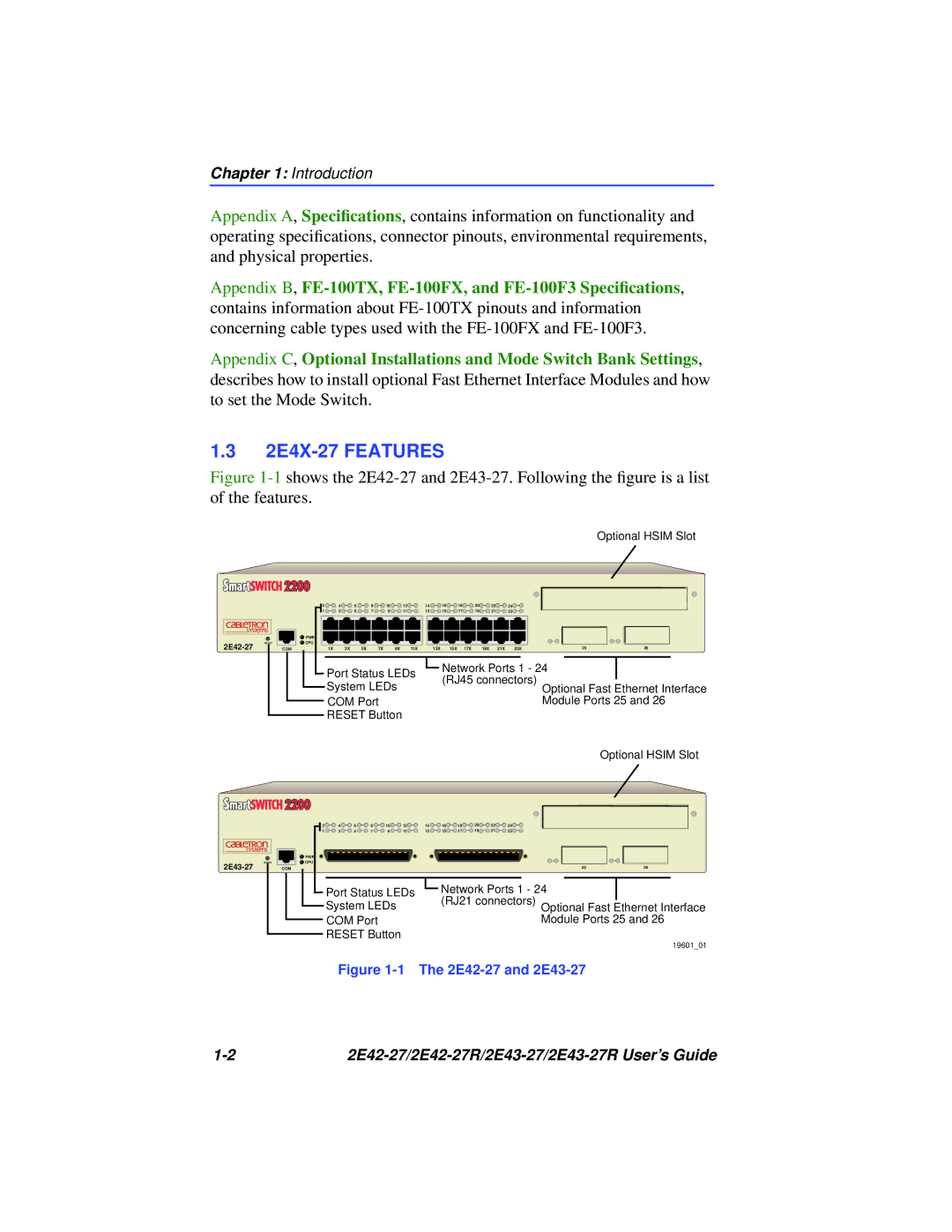
Figure 1-1 shows the 2E42-27 and 2E43-27. Following the figure is a list of the features.
Optional HSIM Slot
RESET
2 | 4 |
| 6 | 8 | 10 | 12 | 14 | 16 | 18 | 20 | 22 | 24 |
|
|
1 | 3 |
| 5 | 7 | 9 | 11 | 13 | 15 | 17 | 19 | 21 | 23 |
|
|
PWR |
|
|
|
|
|
|
|
|
|
|
|
|
|
|
CPU |
|
|
|
|
|
|
|
|
|
|
|
|
|
|
COM | 1X | 3X | 5X | 7X | 9X | 11X | 13X | 15X | 17X | 19X | 21X | 23X | 25 | 26 |
| Port Status LEDs |
| Network Ports 1 - 24 |
| ||||||||||
|
| (RJ45 connectors) |
|
| ||||||||||
| System LEDs |
|
| Optional Fast Ethernet Interface | ||||||||||
|
|
|
|
|
|
|
| |||||||
| COM Port |
|
|
|
|
|
|
|
| Module Ports 25 and 26 | ||||
| RESET Button |
|
|
|
|
|
|
|
|
| ||||
Optional HSIM Slot
RESET
2E43-27
2 | 4 | 6 | 8 | 10 | 12 | 14 | 16 | 18 | 20 | 22 | 24 |
|
1 | 3 | 5 | 7 | 9 | 11 | 13 | 15 | 17 | 19 | 21 | 23 |
|
PWR |
|
|
|
|
|
|
|
|
|
|
|
|
CPU |
|
|
|
|
|
|
|
|
|
|
|
|
COM |
|
|
|
|
|
|
|
|
|
| 25 | 26 |
| Port Status LEDs |
| Network Ports 1 - 24 |
| ||||||||
|
| (RJ21 connectors) Optional Fast Ethernet Interface | ||||||||||
| System LEDs |
|
| |||||||||
| COM Port |
|
|
|
|
|
|
| Module Ports 25 and 26 | |||
| RESET Button |
|
|
|
|
|
|
|
| |||
|
|
|
|
|
|
|
|
|
|
|
| 19601_01 |
| Figure |
| ||||||||||
|
