Chapter 1: Introduction
1.4.10 Optional Features
Options for the
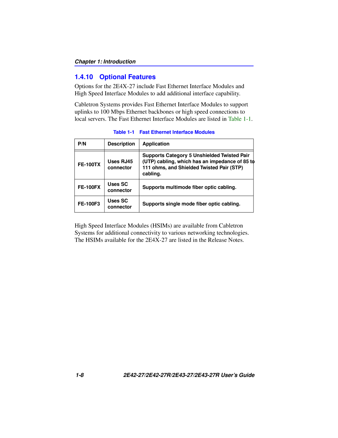
Cabletron Systems provides Fast Ethernet Interface Modules to support uplinks to 100 Mbps Ethernet backbones or high speed connections to local servers. The Fast Ethernet Interface Modules are listed in Table
.
Table 1-1 Fast Ethernet Interface Modules
P/N | Description | Application | |
|
|
| |
|
|
| |
|
| Supports Category 5 Unshielded Twisted Pair | |
Uses RJ45 | (UTP) cabling, which has an impedance of 85 to | ||
connector | 111 ohms, and Shielded Twisted Pair (STP) | ||
| |||
|
| cabling. | |
|
|
| |
Uses SC | Supports multimode fiber optic cabling. | ||
connector | |||
|
| ||
|
|
| |
Uses SC | Supports single mode fiber optic cabling. | ||
connector | |||
|
| ||
|
|
|
High Speed Interface Modules (HSIMs) are available from Cabletron Systems for additional connectivity to various networking technologies. The HSIMs available for the
|