Chapter 3: Installation
Rack Mounting the 2E4X-27
Proceed as follows to install the
1.Remove and discard the four cover screws (two from each side) located along the front edges of each side of the
2.Locate the four
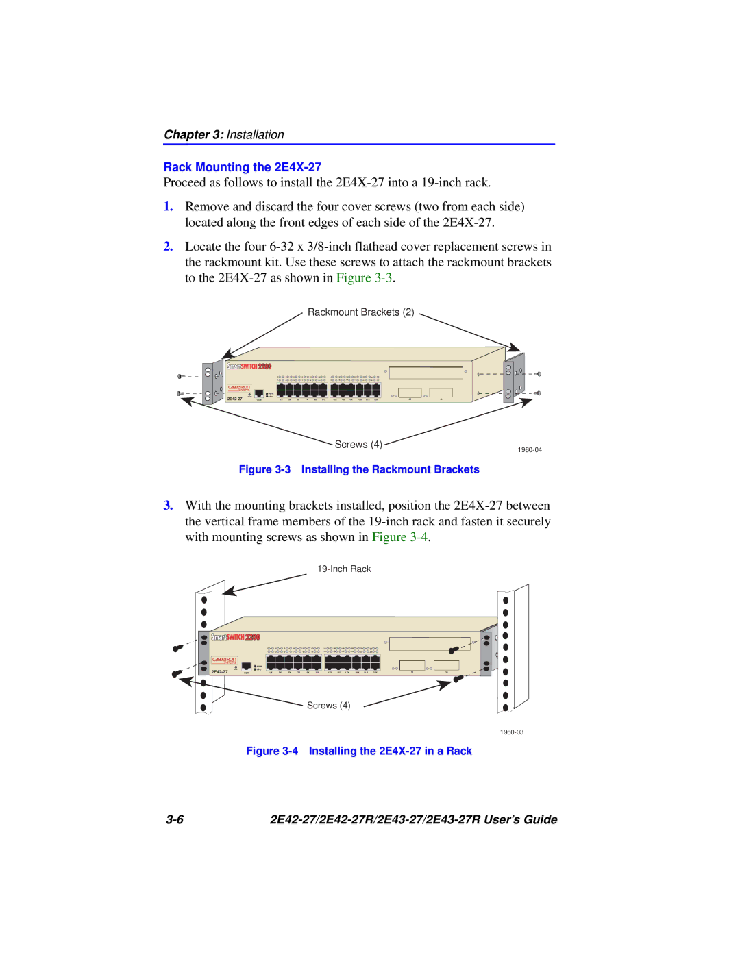
Rackmount Brackets (2)
2 | 4 | 6 | 8 | 10 | 12 | 14 | 16 | 18 | 20 | 22 | 24 |
1 | 3 | 5 | 7 | 9 | 11 | 13 | 15 | 17 | 19 | 21 | 23 |
RESET
![]() PWR
PWR
![]() CPU
CPU
COM | 1X | 3X | 5X | 7X | 9X | 11X | 13X | 15X | 17X | 19X | 21X | 23X | 25 | 26 |
Screws (4)
Figure 3-3 Installing the Rackmount Brackets
3.With the mounting brackets installed, position the
RESET
2 | 4 | 6 | 8 | 10 |
| 12 | 14 | 16 | 18 | 20 | 22 | 24 |
|
|
1 | 3 | 5 | 7 | 9 |
| 11 | 13 | 15 | 17 | 19 | 21 | 23 |
|
|
PWR |
|
|
|
|
|
|
|
|
|
|
|
|
|
|
CPU |
|
|
|
|
|
|
|
|
|
|
|
|
|
|
COM | 1X | 3X | 5X | 7X | 9X | 11X | 13X | 15X | 17X | 19X | 21X | 23X | 25 | 26 |
Screws (4)
Figure 3-4 Installing the 2E4X-27 in a Rack
|