INSTALLATION
3.6CONNECTING THE TRXI TO THE POWER SOURCE
Note: The TRXI has a universal power supply. This allows you to connect the TRXI to power sources from 85 Vac to 264 Vac,
To connect the TRXI to the power source, plug the power cord into a grounded wall outlet. Turn on the power switch at the back panel of the TRXI. Verify that the PWR LED is lit, indicating that the TRXI is receiving power. After the TRXI runs a self test, the CPU LED blinks green indicating normal operation. If the LED remains red, the processor is faulty.
3.7CONNECTING THE NETWORK LOBE PORT CABLING
The
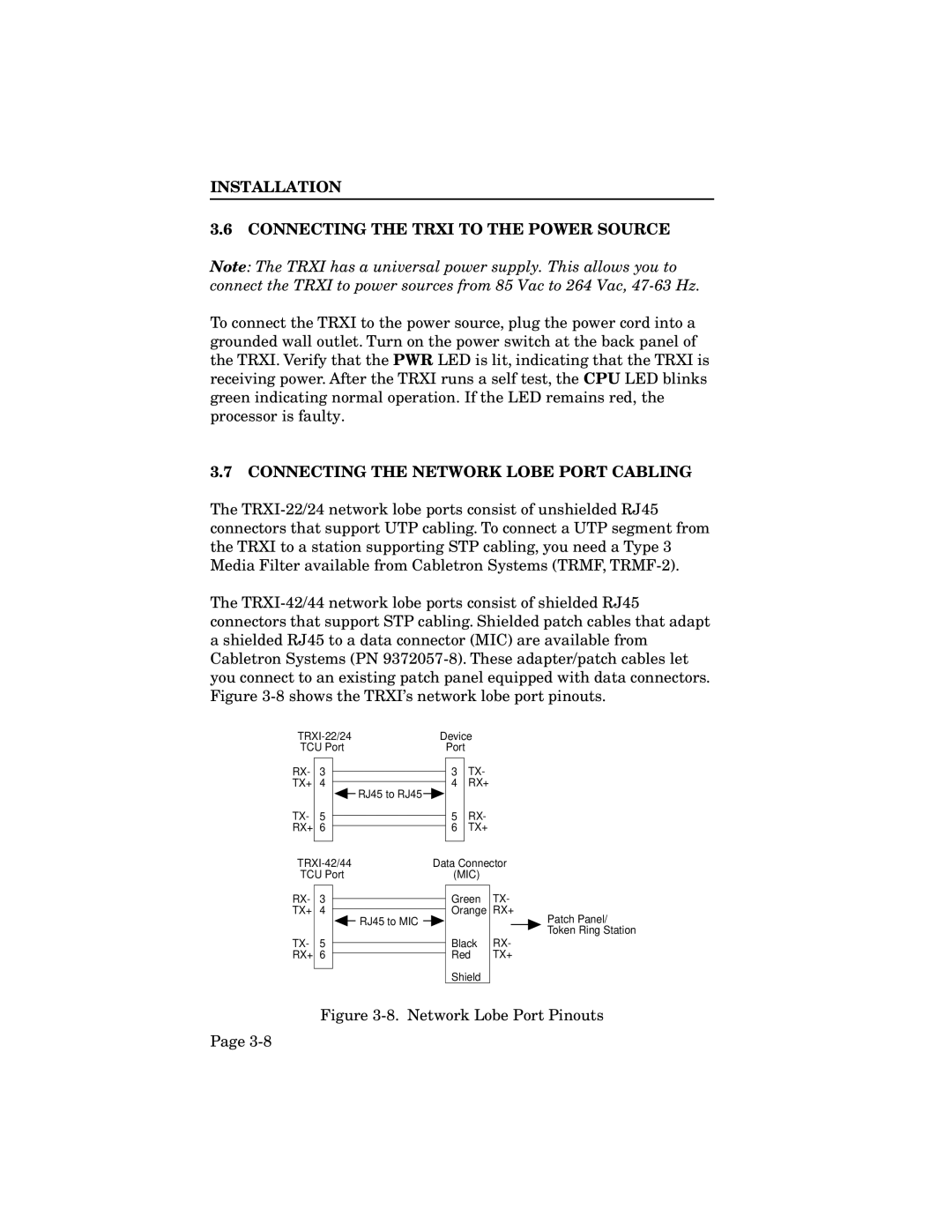
The
Device | |
TCU Port | Port |
RX- 3 TX+ 4
TX- 5 RX+ 6
![]() RJ45 to RJ45
RJ45 to RJ45 ![]()
3TX-
4RX+
5RX-
6TX+
Data Connector | |
TCU Port | (MIC) |
RX- 3 TX+ 4
TX- 5 RX+ 6
![]() RJ45 to MIC
RJ45 to MIC ![]()
Green TX-
Orange RX+
Patch Panel/
Token Ring Station
Black RX-
Red TX+
Shield
Figure 3-8. Network Lobe Port Pinouts
Page