INSTALLATION
To connect a fiber optic link segment to the
1.Remove the protective plastic covers from the fiber optic ports on the applicable port on the module and from the ends of the connectors on each fiber strand.
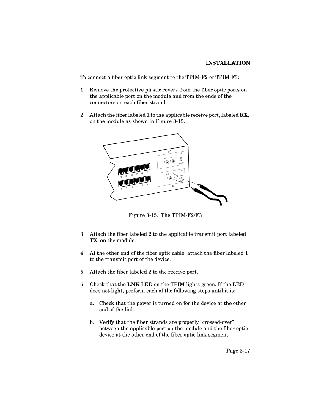
2.Attach the fiber labeled 1 to the applicable receive port, labeled RX, on the module as shown in Figure
RO
18
6
17
5
16
4
15
3
14
2
13
1
RX | TX | LNK |
|
| |
|
| TPIM |
RX | TX |
|
| LNK | |
|
| |
|
| |
|
| TPIM |
| RI |
|
Figure 3-15. The TPIM-F2/F3
3.Attach the fiber labeled 2 to the applicable transmit port labeled TX, on the module.
4.At the other end of the fiber optic cable, attach the fiber labeled 1 to the transmit port of the device.
5.Attach the fiber labeled 2 to the receive port.
6.Check that the LNK LED on the TPIM lights green. If the LED does not light, perform each of the following steps until it is:
a.Check that the power is turned on for the device at the other end of the link.
b.Verify that the fiber strands are properly “crossed-over” between the applicable port on the module and the fiber optic device at the other end of the fiber optic link segment.
Page