IT-2000W
Table of Contents
MS-DOS
Appendix TFORMAT.EXE
Preface
Hardware
Overview Features of System Development Concept
Software
Basic Specifications
RAM
Model Name
Hardware Block Diagram
System Configuration
MS-DOS Main Part
Supported Software
Device Drivers and System Files
Utilities
Windows Driver
Development Tool Libraries
Precautions
Page
Glass cursor
Basic Software Overview Software Configuration
Memory Map
ROM Bios Nand Disk BIOS/VGA Bios
CONFIG.SYS
Drive Configuration
On State OFF Event
Reset Switch On Event
Basic System Operation Overview
OFF State On KEY
Page
On factors
Power on Process
Application Boot Process
Overview
Resume Process
Application Boot Process
System Menu Boot Process
System Menu Boot Process
Resume Process
Setup of Resume Process ON/OFF
On Factors
Auto Power on activated by mounting on the I/O Box
Auto Power on function activated by the Ring signal
Relationship between OFF Factors and on Processes
Normal Suspend Process
Power OFF Process
Critical Suspend
APO
OFF Factors
Battery Operation Scheme
Battery Voltage Monitoring Process
LB3
Low Voltage Level
LB1
LB2
LB1 LB0
Main Battery Voltage Monitoring
Sram Card Battery Voltage Monitoring
Sub-battery Voltage Monitoring
Acquiring Power Status through APM Bios
CSAPM.EXE
Advanced Power Management Process APM
APM Bios
Low Consumption Current Process
Activity monitored by APO
Auto Power OFF Function APO
Auto Backlight OFF Function ABO
About the activity
DOZE/RUN Transit Function
Activity causing RUN/DOZE transition
RUN Doze
Sub-battery replacement
How to Replace or Recharge Batteries
Replacement of Batteries
Main battery replacement
Main Battery Recharge
Vram
Hardware Configuration
Supported Devices Display Unit
About the Display Screen
Software Functions
Contrast Adjustment
Hardware Window
Auto Backlight Control Function
EL Backlight
Manual Backlight ON/OFF Function
Auto Backlight OFF Function
Software Function
Touch Panel
PENMOUSE.COM
Basic Drive
Disk
Types of Disk
RAM Disk
PC Card Drive
ROM Drive
Available Interfaces
Serial Communication
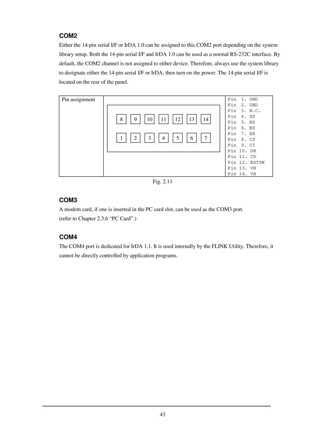
COM2
Recommended PC Cards
How to Format Sram Card and ATA F-ROM Card
PC Card
Hardware Overview
Card Lock Switch
Clock Bios
Clock Timer
Alarm
Buzzer
Setting Volume of Buzzer
Use of Buzzer From the System
DT-9650BCR Pen scanner DT-9656BCR CCD scanner
Barcode Reader
IrDA
Infrared Communication IR
IRQ IRQ1
Keys
Key Layout
Fn key
Sensors
Overview
System Menu
List of Functions
Basic Operation
Function
Key Click Sound Setup
Operation
Buzzer Volume Setup
Contrast Adjustment
Auto Backlight Setup
Auto Power OFF Setup
Touch Panel Calibration
Invalid
Ymodem Utility
About key input during communication
About time stamping of files
Send File to PC one file transmission from IT-2000 to PC
Operations
Receive Files file reception
Page
Flink Command
Operation
About communication with PC
Remote Server remote server mode
System Date/Time Setup
Command Prompt
RAM Disk Size Change
Setting up the RAM disk
Operations with the touch panel are not permitted
Disk Format
Key Operation Function
System Initialization
Password Entry
Loading MS-DOS
YES Reset Button
Example
Example of CONFIG.SYS
How to Write CONFIG.SYS and AUTOEXEC.BAT
DEVICE=C HIMEM.SYS /M2
Ccasioapm
Example of AUTOEXEC.BAT
ATA Card
Card Boot
MS-DOS
Card
Drive G, which is currently enabled, will be disabled
@ECHO OFF
Ewindows
MS-Windows Overview
Demonstration Installation
Installation of MS-Windows
Application Installation
Keyboard Controller Overview
Primary code
Keyboard Control
System Scanning Code
Primary/Secondary Code
Code Table
Secondary code
Fn key
Touch Panel Control Function
ROM Bios
Sensor Control
ABC Auto Backlight Control
Backlight Control
ABC OFF
Transition of Backlight Control Methods
OFF
ABC on
ABO ABC
SYSCALL.DLL
Drivers Overview
VGANC.DRV
Startup Method
System Driver Function
Clock Control Driver Function
None TIME.SYS must be loaded immediately after POWER.EXE
Keypad Driver/Hardware Window Manager Function
PEN Bios
PenMouse Driver Overview
Boot Mouse.drv=penmouse.drv
Virtual Keyboard Driver Function
386Enh Keyboard=vkd.386
Operation Method
System Library main program file Function
Display Driver Function
Page
SIR FIR IRCOMM.DRV IRDA.DRV
COM Driver for IrDA Overview
Frame Layer
IrLAP/IrLMP Layer
DTR DSR DCD RTS CTS
IrCOMM Layer including TinyTP Layer
List of communication functions
Windows 3.1 Communication Functions
Parameter
BuildCommDCB
Return value
ClearCommBreak
CloseComm
EnableCommNotification
Page
EscapeCommFunction
FlushComm
Error values
GetCommError
Page
Members
Comstat structure
GetCommEventMask
OpenComm
Page
GetCommState
ReadComm
SetCommBreak
SetCommEventMask
Page
SetCommState
Ignores RTS at initialization
DCB structure
Oddparity
Evenparity
Markparity
Nonparity
Page
TransmitCommChar
UngetCommChar
WriteComm
Setup example
Setting Up WIN.INI File
DisconnectThresholdTime
MaxBaudRate
SizeWindow
SizeData
DeviceNickName
MaxTurnAroundTime
MinTurnAroundTime
NunBOF
DeviceName
ServiceType
DiscoverCount
Installation Method
Above operations complete the installation procedure 140
Application Development Overview
Page
Application Development Library
Development Environment
Simulation Driver
Program Development Procedure
Creation of Execution File
Debugging Through Simulation
Page
Operation Check on IT-2000 Using COM2KEY/XY
Installation with a PC card
Installation of Application Program
Howto create a card for installation
Installation from a PC
Installation work
Copying application program onto another IT-2000
Simulation Driver
File name
System Library Simulator SysCall.DLL
Monitor window
Installation method
SYSGetABC SYSSetABC
Restictions regarding the IrDA port
Restrictions regarding the COM port
Library
KBC
System Library
List of Libraries
Input
Acquisition of Bios Version
Long SYSGetBiosVersion
Syntax
Int SYSGetMemCapacityint nDevice
Acquisition of Memory Device Size
Dram Nand from Output
Int SYSGetLcdContrastint Winfar *nValue
Setting/Acquisition LCD Contrast
Int SYSSetLcdContrastint nValue
Int SYSLcdContrastUp
Increasing/Decreasing LCD Contrast
Int SYSLcdContrastDown
Int SYSGetCOM2Config
Switching Over COM2 Channel
Int SYSSetCOM2Configint nDevice
Int SYSGetOnEventMask
Setting/Acquisition of Reason Mask for Reboot
Int SYSSetOnEventMaskint nMask
Int SYSRebootint nMode
Reboot Request
Int SYSSetAboTimeint nValue
Setting ABO Time
Int SYSGetAboTime
Acquisition of ABO Time
Int SYSSetABCint nOnOff
Setting ABC Auto Backlight Control Status
Int SYSGetABC
Acquisition of ABC Auto Backlight Control Status
Int SYSSetThresholdOfABCint OnValue, int OffValue
Setting/Acquisition of ABC Threshold
Int SYSGetThresholdOfABCint *OnValue, int *OffValue
Int SYSSetBacklightint nOnOff
Backlight ON/OFF
Int SYSGetBacklight
Acquisition of Backlight Status
Int SYSSetBuzzerVolumeint nVolume
Setting Buzzer Volume
Int SYSGetBuzzerVolume
Acquisition of Buzzer Volume
Output OFF
Int SYSGetDevicePowerint Device
Acquisition of Device Power Status
Int SYSSetDevicePowerint Device, int OnOff
Device Power ON/OFF
Int SYSSetCardLockint OnOff
Software Card Lock
Pcmcia
Int SYSGetConnectorStatusint nType
Acquisition of Connector Status
Int SYSSetKeyClckint OnOff
Key Click Sound ON/OFF
Int SYSGetKeyClick
Acquisition of Key Click Sound Status
Int SYSGetPowerOnFactor
Acquisition of Reboot Reason
Acquisition of OFF Reason
Int SYSGetPowerOffFactor
LBO
Int SYSSetResumeConditionint nCondition
Setting Cancellation of Next Resume Process
Int SYSGetResumeCondition
Acquisition of Cancellation Status of Next Resume Process
Request of Suspend Software-triggered OFF
Void SYSPowerOff
Bios Syntax
Acquisition of Low Battery Voltage Status
Int SYSGetLBStatus
Int SYSSetApoTime int nValue
Setting APO Time
Int SYSGetApoTime
Acquisition of APO Time
Int SYSSetAlarmint hour, int min, int sec
Setting Status of Alarm
Void SYSGetAlarmint *hour, int *min, int *sec
Acquisition of Alarm Setting
Int SYSResetAlarm
Resetting Alarm
Int SYSSetPowerOnAlarmint OnOff
Setting/Acquisition of Power on Alarm
Int SYSGetPowerOnAlarm
Int SYSGetPMStatusvoid
Setting/Acquisition of Status of Power Control Function
Void SYSSetPMStatusint OnOff
Void SYSMakeKeyClick
Setting Key Click Sound on
Keycode
Keypad Library
Timing of accepting a keycode
Repeat function
Input acceptance mode
How to use with a VC application
Toggle function
Page
Page
Page
Page
How to use with VB application
Page
Page
Page
Page
Page
Key acceptance property
Explanation of properties
List of properties
Expansion key number property
Keypad display/non-display property
Expansion keypad number property
Hpic
Expansion keycode property
Expansion key image property
Expansion pad operation property
Registration of expansion key pad Case of VC
Example of expansion pad operation
Case of VB
Deletion of all expansion pads Case of VC
Deletion of expansion key pad In case of VC
OBRLIB.H
OBR Library
Reception Buffer
Data Format
IOBRType = DT-9650 = DT-9656
List of Available Functions
Initialization of OBR
#include obrlib.h Int FAR Pascal export OBROpenint iOBRtype
#include obrlib.h Void FAR Pascal export OBRClose
Release of COM Port
Transmission of Command
#include obrlib.h Int FAR Pascal export OBRStat
Acknowledgment of Received Data
Readout of Received Data
#include obrlib.h Void FAR Pascal export OBRClear
Invalidating Code in Buffer
Setting event of reception completion
OBRSend
Setting Operation Mode / DT-9650BCR
Transmission of normal commands
Transmission of expanded commands
Eeprom
Power-save Mode Control Command
Writing Set Values to Eeprom
OBRSend u OBRSend a
ITF
CODE39 NW-7 ICG
CODE39
WPC
CODE39 C/D
LED on
CODE93 C/D
CODE11 C/D
CODE128 C/D
OBRSend A0
Setting Operation Mode / DT-9656BCR
OBRSend A0 OBRSend Z2
NW-7 Codabar
UPC
EAN
DTF
UPC-E
UPC-A
EAN-8
Code
Not transfer Yes Transfer MSI/Plessey
YMODEM.DLL
Ymodem Library
OpenYMODEM
Error codes
Sub-directory can be the objective of the file transmission
SendByYMODEM
RecieveByYMODEM
SetCommForYMODEM
CloseYMODEM
Setup of the IrDA communication speed MaxBaudRate
WIN.INI setups
Flink Library
Symtax
Setup values of WIN.INI file
Interface to DLL
Void InitFlinkHWND hWndParent, Hinstance hInst
Short DoFLinkForVBshort iArgc, had sArgv
Int DoFlinkint argc, char** argv
File transmission
Commands and options specified by the input parameters
File append
File move
File deletion
Idle start with the optional communication parameters set
Transmission file pathname
Communication Commands File Transmission /S
Function
Options
Parameter setup examples
Request pathname
File Reception /R
Reception directory
Argc = Argv = fl , /R , a Test Dat , d Info Data
Append file pathname
File Append /A
Target file pathname
Deleted file pathname
File Deletion /D
Move source pathname
File Move/File Rename /N
Move destination pathname
Script file name
Idle Start
Wait time for connection establishment
IrDA Environment Setup Commands Wait Time Setup /L
Wait time for data reception/transmission
COM specification
COM Environment Setup /Y
Communication speed
9600 bps
LOW
List of termination codes
End Code Description Category Detail Code Protocol
Utility Overview
Calculator Utility
Touch Panel
Startup Method
Basic Function
Ten Key
Clock Utility
Setup File
Calendar Utility
Remaining Battery Voltage Display Utility
Operation Method
Flink Utility
Wait time until the connection is established
Communication Parameter Setup Command /L=
Command Specification Method
IrDA communication speed
Example of specification
Transmission file pathname
File Transmission /S
Storage destination directory name
Dtest
Example of specifications
Request pathname
File Reception /R
Reception directory
Sub-directory and that have a DAT extension, and all files
Appended file pathname
File Append /A
Target file pathname
Deletion by pathname
File Deletion /D
Option
Move source pathname
File Move/Rename /N
Move destination pathname
Idle Start
275
Termination Codes and Messages
Internal Error
XY Utility
Function and operation method
Using this utility where COM2KEY.EXE is resident
Option
Command
CRC
File name
Other parameters
Termination Codes and Messages
Reverse Video Utility
COM2KEY Utility
If specified by CONFIG.SYS
If executed from DOS prompt line
Start Option
Windows Installation Utility
Windows SYSTEM.INI
Operation at Menu Startup
Outline of WINST.EXE Operations
CLR ESC
WINST.INF
Canadian
Belgian
Brazilia
British
Example of execution on personal computer
Example of Using WINST.EXE
Preparation of necessary files
SYSCALL.DL Windows SYSTEM.INI WIN.INI
WINST.EXE WINST.INF COMM.DRV
Example of execution on the IT-2000
Appendix a TFORMAT.EXE
Card Services CS.EXE
Socket Services SS365SL.EXE
Appendix B PC Card Driver
Sram Card Driver MTSRAM.EXE
Card Identification CARDID.EXE
IDE/ATA Support ATADRV.EXE
Memory Technology Driver MTDDRV.EXE
Card Service Power Management Enabler CSAPM.EXE
Function to Check POWER.EXE
Broadcast for Power Event
INT2Fh
INT15h
Acquisition of Power Status
End of the Manual