Applicable Models: EC-1200 EC-1600 EC-3600 EC-3700
No Display of Cadence (The cadence remains at zero (0) and does not count when the pedal is rotated.) |
|
|
| ||
| Check Method of Causes | Repair Method | Explanation Figures |
|
|
[1] Checking the Control Unit |
|
|
|
| |
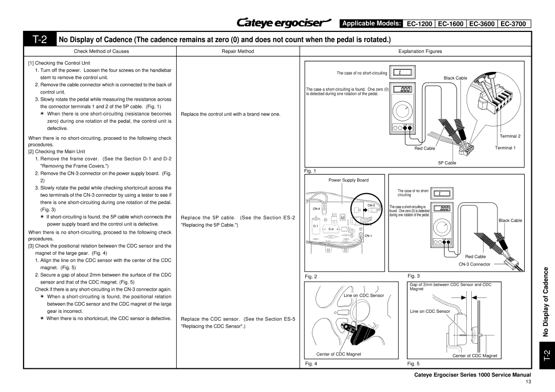
1. Turn off the power. Loosen the four screws on the handlebar | The case of no |
|
|
| |
stem to remove the control unit. |
|
|
| ||
|
| Black Cable |
| ||
2. Remove the cable connector which is connected to the back of | The case a |
|
|
| |
control unit. |
|
|
| ||
is detected during one rotation of the pedal. |
|
|
| ||
|
|
|
| 5 | |
3. Slowly rotate the pedal while measuring the resistance across |
|
| 4 | ||
|
|
| |||
|
|
|
| 3 |
|
the connector terminals 1 and 2 of the 5P cable. (Fig. 1) |
|
| 2 |
| |
|
| 1 |
| ||
t | When there is one | Replace the control unit with a brand new one. |
|
|
|
| zero) during one rotation of the pedal, the control unit is |
|
|
|
|
| defective. |
|
|
|
|
When there is no |
|
| Terminal 2 | ||
|
|
|
| ||
procedures. |
| Red Cable | Terminal 1 | ||
[2] Checking the Main Unit |
| ||||
|
|
|
| ||
1. Remove the frame cover. (See the Section |
|
|
|
| |
"Removing the Frame Covers.") |
|
| 5P Cable |
| Fig. 1 |
| |
2. Remove the |
|
| |
|
|
| |
2) |
|
| Power Supply Board |
3. Slowly rotate the pedal while checking shortcircuit across the |
|
| The case of no short- |
two terminals of the |
|
| |
|
| circuiting | |
there is one |
|
| The case a |
(Fig. 3) |
|
| |
|
| found. One zero (0) is detected | |
t If | Replace the 5P cable. | (See the Section | during one rotation of the pedal. |
Black Cable | |||
power supply board and the control unit is defective. | "Replacing the 5P Cable.") |
|
|
When there is no |
|
|
|
procedures. |
|
|
|
[3] Check the positional relation between the CDC sensor and the |
|
|
|
magnet of the large gear. (Fig. 4) |
|
| Red Cable |
1. Align the line on the CDC sensor with the center of the CDC |
|
| |
|
| ||
magnet. (Fig. 5) |
|
| |
|
|
| |
2. Secure a gap of about 2mm between the surface of the CDC |
| Fig. 2 | Fig. 3 |
sensor and that of the CDC magnet. (Fig. 5) |
|
| Gap of 2mm between CDC Sensor and CDC |
Check if there is any |
|
| |
|
| Magnet | |
t When a |
|
| Line on CDC Sensor |
|
|
| |
between the CDC sensor and the CDC magnet of the large |
|
|
|
gear is incorrect. |
|
| Line on CDC Sensor |
t When there is no shortcircuit, the CDC sensor is defective. | Replace the CDC sensor. | (See the Section |
|
| "Replacing the CDC Sensor".) |
| |
|
|
|
|
|
|
|
|
|
|
|
|
|
|
|
|
|
|
|
|
|
|
|
|
|
|
|
|
|
|
|
|
|
Ce | nter of CDC Mag | net | Center of CDC Magnet | |||||||
|
|
|
| |||||||
Fig. 4 | Fig. 5 | |||||||||
Cateye Ergociser Series 1000 Service Manual
T-2 No Display of Cadence
13
