Applicable Models: EC-1200 


MS-1 Replacing the Workload Unit (w/o Flywheel) (2)
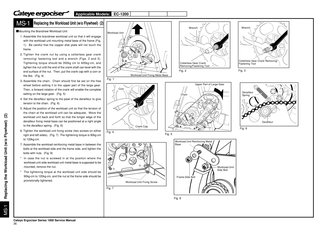
àMounting the Brandnew Workload Unit
1. Assemble the brandnew workload unit so that it will engage |
with the workload unit mounting metal base of the frame (Fig. |
1). Be careful that the copper disk plate will not touch the |
frame. |
2. Tighten the crank nut by using a cotterless gear crank |
removing/ fastening tool and a wrench (Figs. 2 and 3). |
Tightening torque should be 350kg cm to 400kg·cm, and |
tighten the nut until the end of the crank shaft can level with the |
end surface of the nut. Then, put the crank cap with a coin or |
the like. (Fig. 4) |
Workload Unit
Workload Unit Fixing Metal Base
Wrench
Cotterless Gear Crank Removing/Fastening Tool
Fig. 2
Wrench
Cotterless Gear Crank Removing/ Fastening Tool
Fig. 3
the Workload Unit (w/o Flywheel) (2)
3. | Assemble the chain. Chain should first be set on the free |
| wheel before setting it to the upper part of the large gear. |
| Then, a forward rotation of the crank will enable the complete |
| setting on the large gear. (Fig. 5) |
4. | Set the derailleur spring to the pawl of the derailleur to give |
| tension to the chain. (Fig. 6) |
5. | Adjust the position of the workload unit so that the tension of |
| the chain at the workload unit can be adequate. Move the |
| workload unit back and forth so that the longer edge of the |
| derailleur fixing metal base can be positioned at a right angle |
| to the derailleur spring. (Fig. 6) |
6. | Tighten the workload unit fixing screw (two screws on either |
| right and left sides). (Fig. 7) The tightening torque is 90kg·cm |
| to 120kg·cm. |
7. | Assemble the workload reinforcing metal base in between the |
| bolts at the workload side and the frame side, and tighten the |
| bolts with nuts. (Fig. 8) |
*In case the nut is screwed in at the position where the
*The tightening torque at the workload unit side should be 90kg·cm to 120kg·cm, and the nut at the frame side should be provisionally tightened.
Fig. 1
Coin
Crank Cap
Fig. 4
Workload Unit Fixing Screw
Upper Part of Large Gear
Chain
Fig. 5
Workload Unit Reinforcing Metal
Base
![]()
![]()
Side Bolt
Derailleur
Spring
Derailleur
Fig. 6
Fig. 7
Fig. 8
Cateye Ergociser Series 1000 Service Manual
36
