Applicable Models: EC-1200 EC-1600 EC-3600 EC-3700
ES-5 Replacing the CDC Sensor
1. | Remove the frame cover. (See the Sections |
| "Removing the Frame Covers.") |
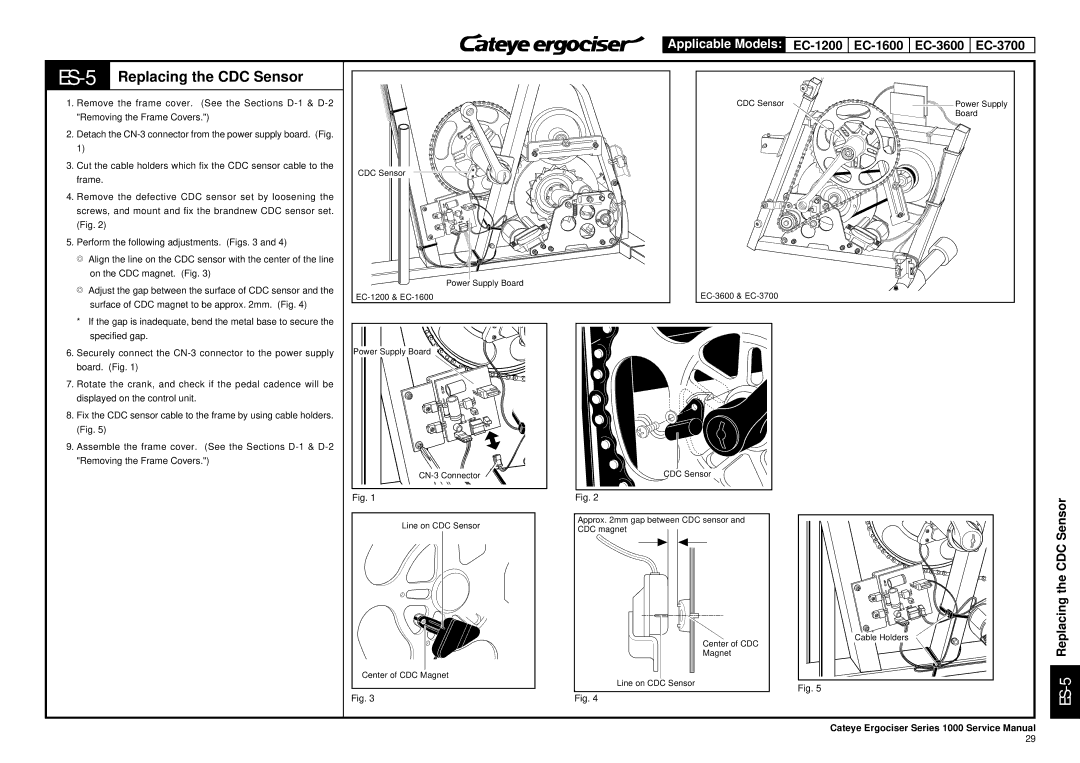
2. | Detach the |
| 1) |
3. | Cut the cable holders which fix the CDC sensor cable to the |
| frame. |
4. | Remove the defective CDC sensor set by loosening the |
| screws, and mount and fix the brandnew CDC sensor set. |
| (Fig. 2) |
5. | Perform the following adjustments. (Figs. 3 and 4) |
| T Align the line on the CDC sensor with the center of the line |
| on the CDC magnet. (Fig. 3) |
| T Adjust the gap between the surface of CDC sensor and the |
| surface of CDC magnet to be approx. 2mm. (Fig. 4) |
| * If the gap is inadequate, bend the metal base to secure the |
| specified gap. |
CDC Sensor
Power Supply Board
CDC Sensor | Power Supply |
| Board |
ON
OFF
6. | Securely connect the |
| board. (Fig. 1) |
7. | Rotate the crank, and check if the pedal cadence will be |
| displayed on the control unit. |
8. | Fix the CDC sensor cable to the frame by using cable holders. |
| (Fig. 5) |
9. | Assemble the frame cover. (See the Sections |
| "Removing the Frame Covers.") |
Power Supply Board ![]()
Fig. 1
Line on CDC Sensor
Center of CDC Magnet
Fig. 3
![]() CDC Sensor
CDC Sensor
Fig. 2
Approx. 2mm gap between CDC sensor and CDC magnet
Center of CDC
Magnet
Line on CDC Sensor
Fig. 4
Cable Holders
Fig. 5
ES-5 Replacing the CDC Sensor
Cateye Ergociser Series 1000 Service Manual
29
