Applicable Models: EC-1200 EC-1600 EC-3600 EC-3700
MS-8 Replacing the Crank Set (2)
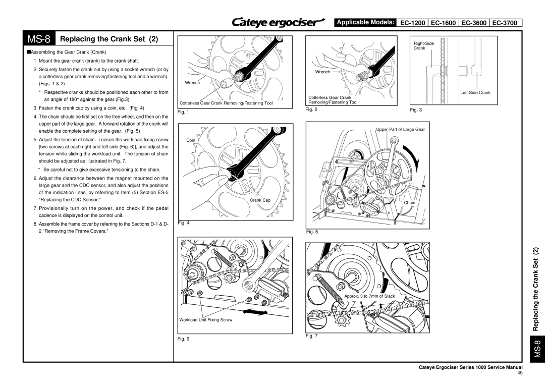
àAssembling the Gear Crank (Crank)
1. | Mount the gear crank (crank) to the crank shaft. |
2. | Securely fasten the crank nut by using a socket wrench (or by |
| a cotterless gear crank removing/fastening tool and a wrench). |
| (Figs. 1 & 2) |
| * Respective cranks should be positioned each other to from |
| an angle of 180° against the gear.(Fig.3) |
3. | Fasten the crank cap by using a coin, etc. (Fig. 4) |
4. | The chain should be first set on the free wheel, and then on the |
| upper part of the large gear. A forward rotation of the crank will |
Wrench
Cotterless Gear Crank Removing/Fastening Tool
Fig. 1
Wrench
Cotterless Gear Crank Removing/Fastening Tool
Fig. 2
Crank
Fig. 3
| enable the complete setting of the gear. (Fig. 5) |
5. | Adjust the tension of chain. Loosen the workload fixing screw |
| [two screws at each right and left side (Fig. 6)], and adjust the |
| tension while sliding the workload unit. The tension of chain |
| should be adjusted as illustrated in Fig. 7. |
| * Be careful not to give excessive tensioning to the chain. |
6. Adjust the clearance between the magnet mounted on the | |
| large gear and the CDC sensor, and also adjust the positions |
| of the indication lines, by referring to Item (5) Section |
| "Replacing the CDC Sensor." |
7. | Provisionally turn on the power, and check if the pedal |
| cadence is displayed on the control unit. |
8. | Assemble the frame cover by referring to the Sections |
| 2 "Removing the Frame Covers." |
Coin
Crank Cap
Fig. 4
Workload Unit Fixing Screw
Fig. 6
Upper Part of Large Gear
Chain
Fig. 5
Approx. 3 to 7mm of Slack
Fig. 7
MS-8 Replacing the Crank Set (2)
Cateye Ergociser Series 1000 Service Manual
45