Applicable Models:
Perform the positional correction of the core slit section after detaching the frame cover and turning off the power. (See the Sections
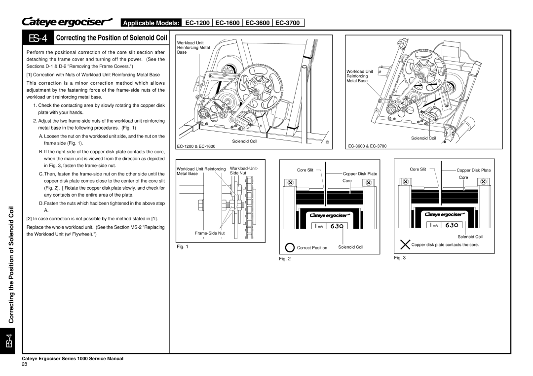
[1] Correction with Nuts of Workload Unit Reinforcing Metal Base
This correction is a minor correction method which allows adjustment by the fastening force of the
1. | Check the contacting area by slowly rotating the copper disk |
| plate with your hands. |
2. | Adjust the two |
| metal base in the following procedures. (Fig. 1) |
| A. Loosen the nut on the workload unit side, and the nut on the |
| frame side (Fig. 1). |
| B. If the right side of the copper disk plate contacts the core, |
| when the main unit is viewed from the direction as depicted |
| in Fig. 3, fasten the |
Workload Unit
Reinforcing Metal
Base
Solenoid Coil
Workload Unit
Reinforcing
Metal Base
Solenoid Coil
ON
OFF
C. Then, fasten the |
copper disk plate comes close to the center of the core slit |
(Fig. 2). [ Rotate the copper disk plate slowly, and check for |
any contacts on the entire area of the plate. |
D. Fasten the nuts which had been tightened in the above step |
A. |
[2] In case correction is not possible by the method stated in [1]. |
Replace the whole workload unit. (See the Section
Workload Unit Reinforcing | ||||||||||||||||
Metal Base |
|
|
| Side Nut |
|
|
| |||||||||
| ||||||||||||||||
|
|
|
|
| ||||||||||||
|
|
|
|
|
|
| ||||||||||
|
|
|
|
|
|
|
|
|
|
|
|
|
|
|
|
|
|
|
|
|
|
|
|
|
|
|
|
|
|
|
|
|
|
|
|
|
|
|
|
|
|
|
|
|
|
|
|
|
|
|
|
|
|
|
|
|
|
|
|
|
|
|
|
|
|
|
|
|
|
|
|
|
|
|
|
|
|
|
|
|
|
|
|
|
|
|
|
|
|
|
|
|
|
|
|
|
|
|
|
|
|
|
|
|
|
|
|
|
|
|
|
|
|
|
|
|
|
|
|
|
|
|
|
|
|
|
|
|
|
|
|
|
|
|
|
|
|
|
|
|
|
|
|
|
|
|
|
|
|
|
|
|
|
|
|
|
|
|
|
|
|
|
|
|
|
|
|
|
|
|
|
|
|
|
|
|
|
|
|
|
|
|
|
|
|
|
|
|
|
|
|
|
|
|
|
|
|
|
|
|
|
|
|
|
|
|
|
|
|
|
|
|
|
|
|
|
|
|
|
|
|
|
|
|
|
|
|
|
|
|
|
|
|
|
|
|
|
|
|
|
|
|
|
|
|
|
|
|
|
|
|
|
|
|
|
|
|
|
|
|
|
|
|
|
|
|
|
|
|
|
|
|
|
|
|
|
|
|
|
|
|
|
|
|
|
|
|
|
Fig. 1
Core Slit
Copper Disk Plate
Core
I mA
Correct Position | Solenoid Coil |
Fig. 2
| Core Slit |
|
|
| Copper Disk Plate | |||||||
|
|
|
| |||||||||
|
|
|
|
|
|
| Core |
|
| |||
|
|
|
|
|
|
|
|
|
|
|
|
|
|
|
|
|
|
|
|
|
|
|
|
|
|
|
|
|
|
|
|
|
|
|
|
|
|
|
I mA
Solenoid Coil
Copper disk plate contacts the core.
Fig. 3
Cateye Ergociser Series 1000 Service Manual
28
