Applicable Models:
D-1 Removing the Frame Covers
Upright Type
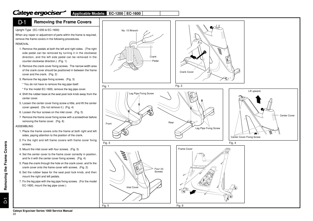
When any repair or adjustment of parts within the frame is required, remove the frame covers in the following procedures.
REMOVAL
1.Remove the pedals at both the left and right sides. (The right side pedal can be removed by turning it in the clockwise direction, and the left side pedal can be removed in the
2.Remove the crank cover fixing screws. The
3.Remove the leg pipe fixing screws. (Fig. 3)
*You do not have to remove the leg pipe itself.
*For the model
4.Shift the rubber base at the seat post lock knob away from the center cover.
5.Loosen the center cover fixing screw a little, and lift the center cover upward. (Do not remove it.) (Fig. 4)
6.Loosen the four screws on the inlet cover. (Fig. 5)
7.Remove the frame cover fixing screw with a screwdriver before removing the frame cover. (Fig. 6)
ASSEMBLING
No. 15 Wrench
Crank
Pedal
Crank Cover
Fig. 1 | Fig. 2 |
Leg Pipe Fixing Screw
ON
OFF
Front | Rear |
|
Leg Pipe Fixing Screw
Lift upward.
Center Cover
D-1 Removing the Frame Covers
1.Place the frame covers onto the frame at both right and left sides, paying attention to the position of the crank.
2.Fix the right and left frame covers with frame cover fixing screws.
3.Mount the inlet cover with four screws. (Fig. 5)
4.Set the center cover to the frame cover correctly in position, and fix it with the center cover fixing screws. (Fig. 4)
5.Pass the crank through the hole on the crank cover, and fix the crank cover onto the frame cover with screws. (Fig. 2)
6.Set the rubber base for the seat post lock knob, and then mount the right and left pedals.
7.Fix the leg pipe with the leg pipe fixing screws. (For the model
Center Cover Fixing Screw
Fig. 3 | Fig. 4 |
Frame Cover
ON
OFF | Four (4) |
| Screws |
Inlet Cover
Fig. 5 | Fig. 6 |
Cateye Ergociser Series 1000 Service Manual
22
