Applicable Models: EC-1200 EC-1600 EC-3600 EC-3700
ES-1 Replacing the Wiring within the Frame
[A] Removing the Wiring Parts | |
1. | Remove the frame cover. (See the Sections |
| "Removing the Frame Covers.") |
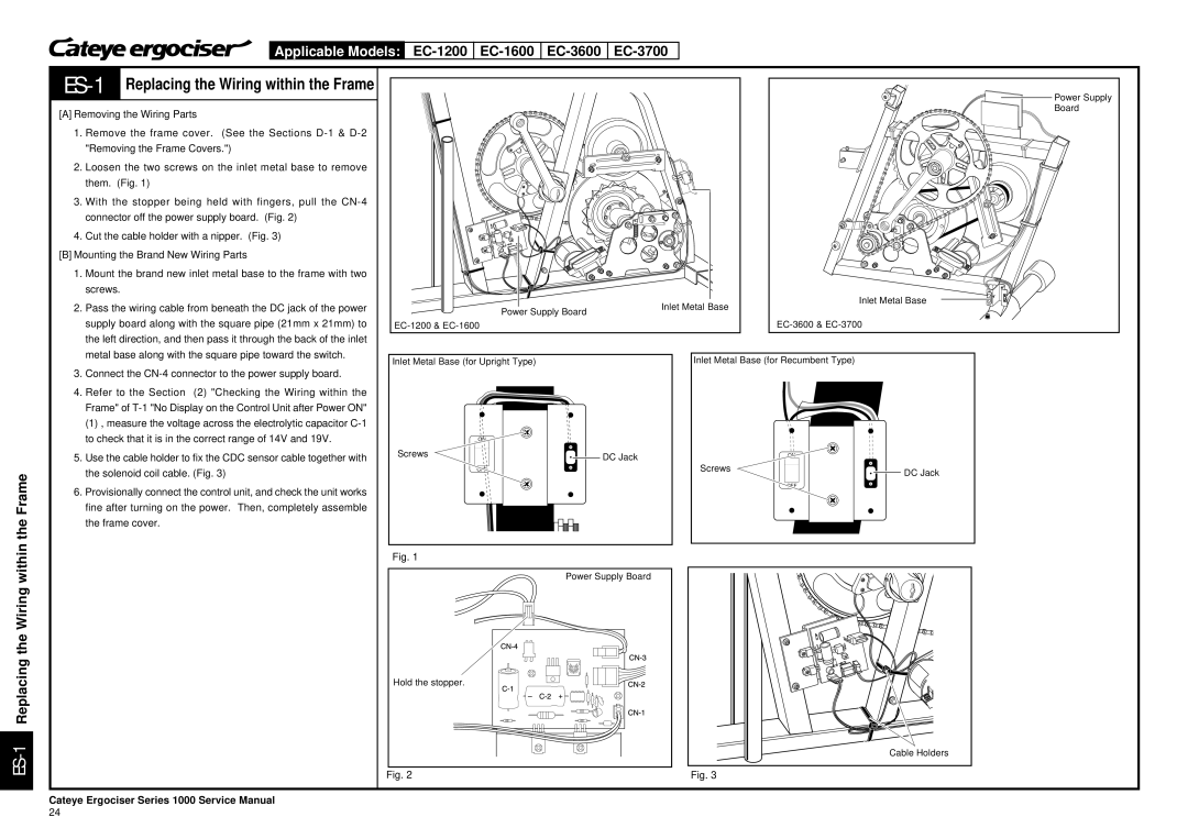
2. | Loosen the two screws on the inlet metal base to remove |
| them. (Fig. 1) |
3. | With the stopper being held with fingers, pull the |
| connector off the power supply board. (Fig. 2) |
4. | Cut the cable holder with a nipper. (Fig. 3) |
[B] Mounting the Brand New Wiring Parts | |
1. | Mount the brand new inlet metal base to the frame with two |
| screws. |
2. | Pass the wiring cable from beneath the DC jack of the power |
| supply board along with the square pipe (21mm x 21mm) to |
| the left direction, and then pass it through the back of the inlet |
| metal base along with the square pipe toward the switch. |
|
|
|
|
|
|
|
|
|
| Inlet Metal Base |
|
|
|
|
|
|
|
|
|
| |
|
|
|
|
|
|
|
|
|
| |
|
|
|
|
|
|
|
|
|
| |
|
|
|
|
|
|
|
|
|
| |
|
|
|
|
|
|
|
|
|
| |
|
|
|
|
|
|
|
|
|
| |
|
|
|
|
|
|
|
|
|
| |
|
|
|
|
|
| Inlet Metal Base |
| |||
|
|
| Power Supply Board |
| ||||||
|
|
|
| |||||||
|
|
|
|
|
|
| ||||
|
|
|
|
|
|
|
|
|
|
|
Power Supply
Board
ON
OFF
the Frame
3. | Connect the |
4. | Refer to the Section (2) "Checking the Wiring within the |
| Frame" of |
| (1) , measure the voltage across the electrolytic capacitor |
| to check that it is in the correct range of 14V and 19V. |
5. | Use the cable holder to fix the CDC sensor cable together with |
| the solenoid coil cable. (Fig. 3) |
6. | Provisionally connect the control unit, and check the unit works |
| fine after turning on the power. Then, completely assemble |
| the frame cover. |
Inlet Metal Base (for Upright Type)
ON
Screws | DC Jack |
| |
| OFF |
Inlet Metal Base (for Recumbent Type)
ON
Screws | DC Jack |
| |
| OFF |
ES-1 Replacing the Wiring within
Fig. 1
Power Supply Board
Hold the stopper.
Cable Holders
Fig. 2 | Fig. 3 |
Cateye Ergociser Series 1000 Service Manual
24
