Chapter 1 Overview
IP Camera Physical Details
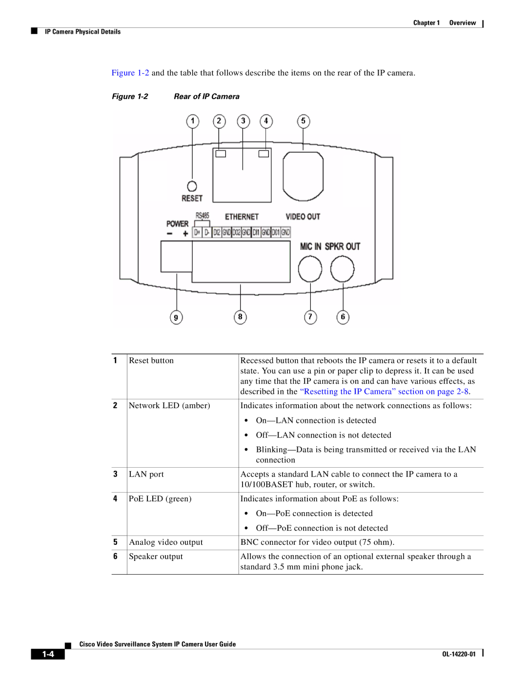
Figure 1-2 and the table that follows describe the items on the rear of the IP camera.
Figure 1-2 Rear of IP Camera
1 | Reset button | Recessed button that reboots the IP camera or resets it to a default |
|
| state. You can use a pin or paper clip to depress it. It can be used |
|
| any time that the IP camera is on and can have various effects, as |
|
| described in the “Resetting the IP Camera” section on page |
|
|
|
2 | Network LED (amber) | Indicates information about the network connections as follows: |
|
| • |
|
| • |
|
| • |
|
| connection |
|
|
|
3 | LAN port | Accepts a standard LAN cable to connect the IP camera to a |
|
| 10/100BASET hub, router, or switch. |
|
|
|
4 | PoE LED (green) | Indicates information about PoE as follows: |
|
| • |
|
| • |
|
|
|
5 | Analog video output | BNC connector for video output (75 ohm). |
|
|
|
6 | Speaker output | Allows the connection of an optional external speaker through a |
|
| standard 3.5 mm mini phone jack. |
|
|
|
Cisco Video Surveillance System IP Camera User Guide
| ||
|