Chapter 1 Overview
|
|
|
|
| IP Camera Physical Details |
|
|
|
|
|
|
|
|
7 | Microphone input | Allows the connection of an optional external microphone (with |
| |||
|
|
|
| |||
|
|
| Microphones that are designed for use with PCs usually are |
| ||
|
|
| compatible with this input jack. |
| ||
|
|
| Connecting an external microphone disables the internal |
| ||
|
|
| microphone on the IP camera. |
| ||
|
|
|
|
| ||
8 | GPIO ports |
| General purpose input/output (GPIO) terminal block that includes |
| ||
|
|
| a |
| ||
|
|
| ports (labeled DO1, DO2), and 3 ground ports (labeled GND). |
| ||
|
|
|
| |||
9 | Power input | Provides for the connection of an optional 12 V, 1 amp DC power |
| |||
|
|
| adapter. |
| ||
|
|
|
|
|
|
|
|
|
| Caution Use only the Cisco specified power supply adapter. |
| ||
|
|
|
|
|
|
|
|
|
|
|
|
|
|
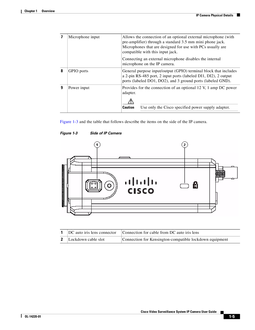
Figure 1-3 and the table that follows describe the items on the side of the IP camera.
Figure 1-3 Side of IP Camera
1 | DC auto iris lens connector | Connection for cable from DC auto iris lens |
|
|
|
2 | Lockdown cable slot | Connection for |
|
|
|
Cisco Video Surveillance System IP Camera User Guide
|
| ||
|
|