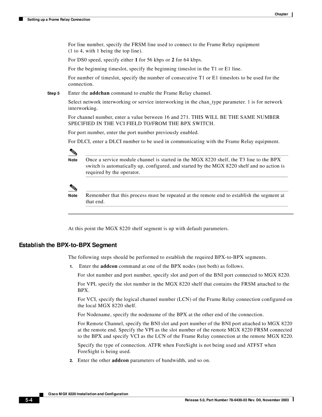
MGX 8220 specifications
The Cisco Systems MGX 8220 is a versatile, high-performance media gateway that has become an integral component in the telecommunications infrastructure. Designed to facilitate the transition from traditional circuit-switched networks to advanced packet-switched environments, the MGX 8220 supports a wide array of voice, video, and data services, making it an essential tool for service providers and enterprises seeking to enhance their network capabilities.One of the key features of the MGX 8220 is its robust signaling and media processing capabilities. Equipped with support for both Voice over IP (VoIP) and traditional telephony protocols, this gateway enables seamless integration of different communication formats. It boasts a modular architecture, which allows for the addition or removal of various line cards to meet changing demands and technology advancements. This modularity provides operators with the flexibility to scale their services without significant overhauls to their existing infrastructure.
The MGX 8220 is capable of delivering high-density media handling for a multitude of services. With its support for ATM and IP networks, the gateway can handle TDM (Time-Division Multiplexing) to packet voice conversions efficiently. It is designed to optimize network resources by dynamically allocating bandwidth based on traffic requirements, thus ensuring efficient use of network resources and improved performance.
Another significant characteristic of the MGX 8220 is its enhanced quality of service (QoS) features. This capability ensures that voice and video traffic is prioritized appropriately, minimizing latency and jitter while maximizing overall call quality. By employing sophisticated traffic management techniques, the MGX 8220 can deliver a superior user experience, which is critical for any service provider aiming to offer competitive communication solutions.
Furthermore, the gateway includes built-in security features to protect against unauthorized access and ensure the integrity of sensitive data. This includes encryption for voice and video transmission, as well as support for secure signaling protocols.
Overall, the Cisco Systems MGX 8220 stands out as a comprehensive media gateway solution, providing essential functionalities for modern communication needs. Its combination of modularity, high-density processing, effective QoS management, and security features makes it a compelling choice for organizations looking to modernize their telecommunications infrastructure while ensuring reliability and performance. As businesses continue to evolve and demand more from their networks, the MGX 8220 offers a pathway to future-ready communications.

