5. Installation
▫VGA Monitor Connection
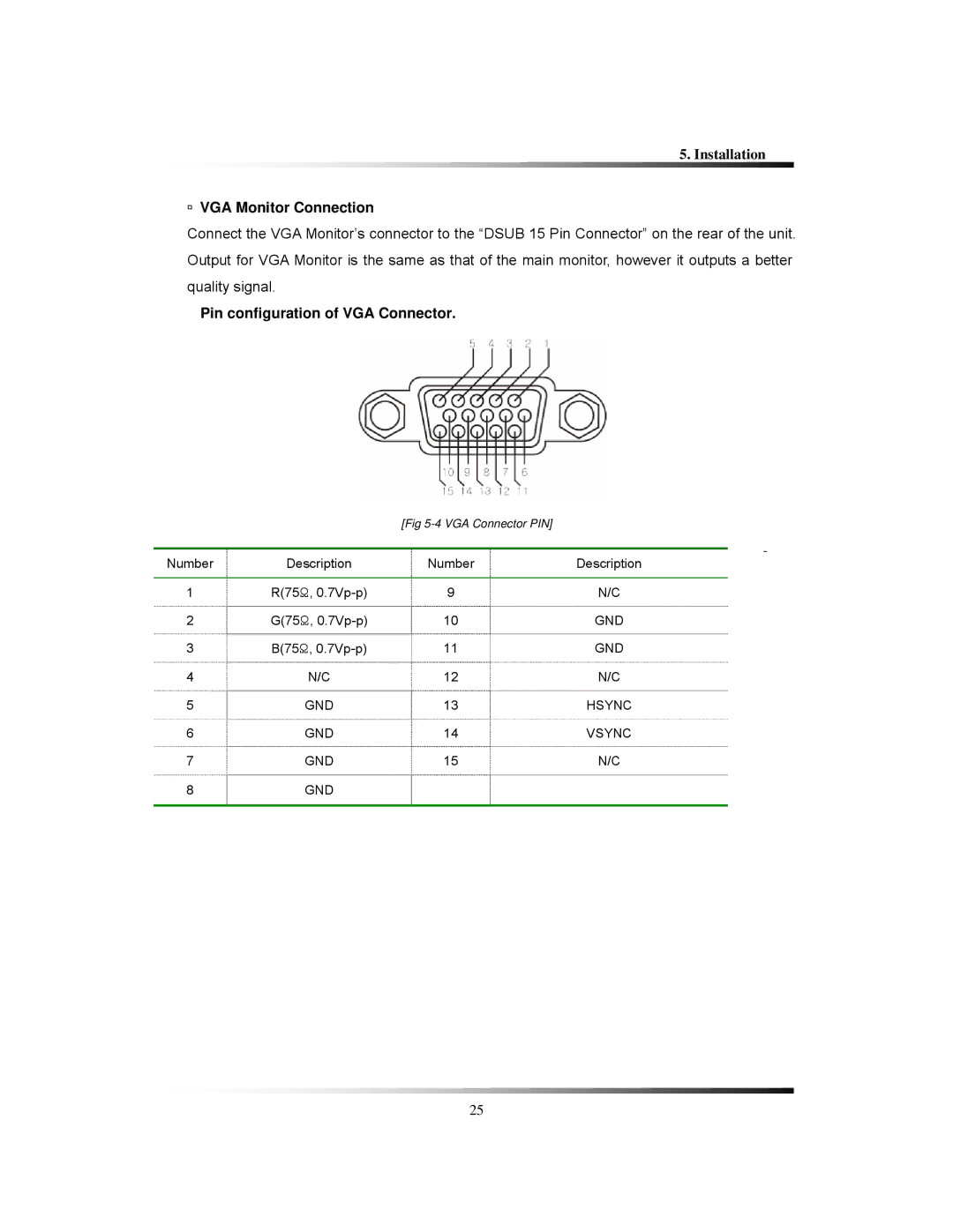
Connect the VGA Monitor’s connector to the “DSUB 15 Pin Connector” on the rear of the unit. Output for VGA Monitor is the same as that of the main monitor, however it outputs a better quality signal.
Pin configuration of VGA Connector.
[Fig
|
|
|
| - |
Number | Description | Number |
| |
Description | ||||
|
|
|
|
|
1 | R(75Ω, | 9 | N/C | |
2 | G(75Ω, | 10 | GND | |
3 | B(75Ω, | 11 | GND | |
4 | N/C | 12 | N/C | |
5 | GND | 13 | HSYNC | |
6 | GND | 14 | VSYNC | |
7 | GND | 15 | N/C | |
8 | GND |
|
|
|
|
|
|
|
|
25