CY7C65113C
During a reset, the contents of the Global Interrupt Enable Register and USB End Point Interrupt Enable Register are cleared, effectively disabling all interrupts,
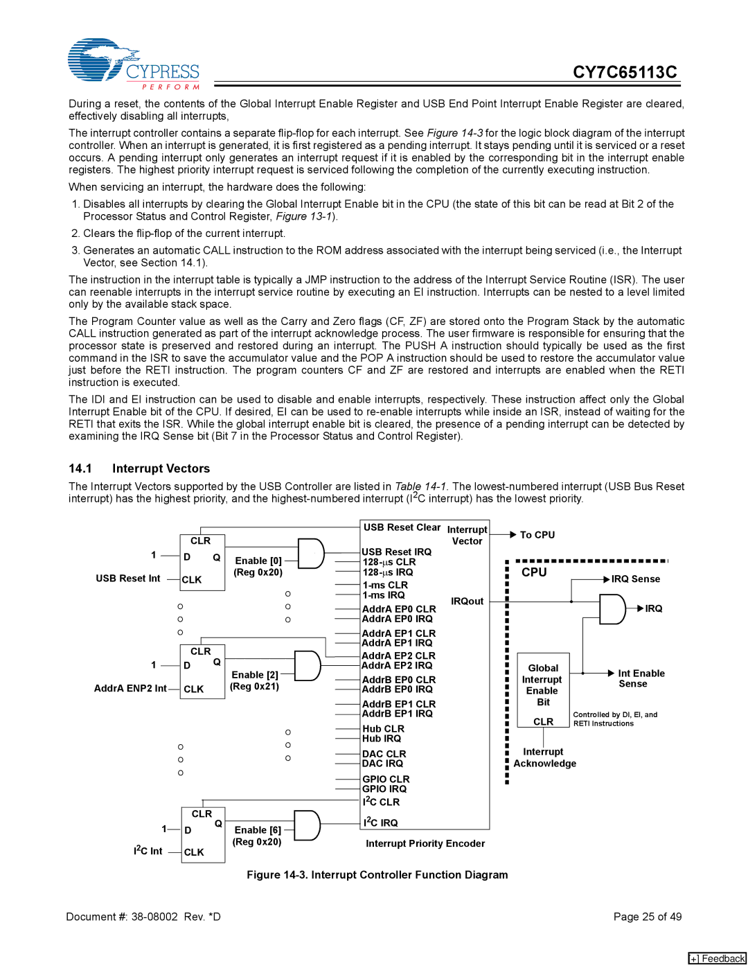
The interrupt controller contains a separate
When servicing an interrupt, the hardware does the following:
1.Disables all interrupts by clearing the Global Interrupt Enable bit in the CPU (the state of this bit can be read at Bit 2 of the Processor Status and Control Register, Figure
2.Clears the
3.Generates an automatic CALL instruction to the ROM address associated with the interrupt being serviced (i.e., the Interrupt Vector, see Section 14.1).
The instruction in the interrupt table is typically a JMP instruction to the address of the Interrupt Service Routine (ISR). The user can reenable interrupts in the interrupt service routine by executing an EI instruction. Interrupts can be nested to a level limited only by the available stack space.
The Program Counter value as well as the Carry and Zero flags (CF, ZF) are stored onto the Program Stack by the automatic CALL instruction generated as part of the interrupt acknowledge process. The user firmware is responsible for ensuring that the processor state is preserved and restored during an interrupt. The PUSH A instruction should typically be used as the first command in the ISR to save the accumulator value and the POP A instruction should be used to restore the accumulator value just before the RETI instruction. The program counters CF and ZF are restored and interrupts are enabled when the RETI instruction is executed.
The IDI and EI instruction can be used to disable and enable interrupts, respectively. These instruction affect only the Global Interrupt Enable bit of the CPU. If desired, EI can be used to
14.1Interrupt Vectors
The Interrupt Vectors supported by the USB Controller are listed in Table
1
USB Reset Int
1
AddrA ENP2 Int
1 I2C Int
CLR |
|
| USB Reset Clear | Interrupt | To CPU |
|
|
|
| Vector |
| ||
|
| USB Reset IRQ |
|
| ||
D | Q | Enable [0] |
|
|
| |
| CPU |
| ||||
CLK |
| (Reg 0x20) |
| IRQ Sense | ||
|
|
|
| |||
|
|
|
|
|
| |
|
|
| IRQout |
|
| |
|
|
| AddrA EP0 CLR |
| IRQ | |
|
|
|
|
| ||
|
|
| AddrA EP0 IRQ |
|
|
|
|
|
| AddrA EP1 CLR |
|
|
|
CLR |
|
| AddrA EP1 IRQ |
|
|
|
Q |
| AddrA EP2 CLR |
|
|
| |
D | Enable [2] | AddrA EP2 IRQ |
| Global | Int Enable | |
|
| |||||
|
| AddrB EP0 CLR |
| Interrupt | ||
CLK |
| (Reg 0x21) |
| Sense | ||
| AddrB EP0 IRQ |
| Enable | |||
|
|
| AddrB EP1 CLR |
| Bit |
|
|
|
| AddrB EP1 IRQ |
| CLR | Controlled by DI, EI, and |
|
|
| Hub CLR |
| RETI Instructions | |
|
|
|
|
|
| |
|
|
| Hub IRQ |
| Interrupt |
|
|
|
| DAC CLR |
|
| |
|
|
| DAC IRQ |
| Acknowledge | |
|
|
| GPIO CLR |
|
|
|
|
|
| GPIO IRQ |
|
|
|
CLR |
|
| I2C CLR |
|
|
|
Q |
| I2C IRQ |
|
|
| |
D | Enable [6] |
|
|
| ||
|
|
|
|
| ||
CLK |
| (Reg 0x20) | Interrupt Priority Encoder |
|
| |
|
|
|
|
|
| |
Figure 14-3. Interrupt Controller Function Diagram
Document #: | Page 25 of 49 |
[+] Feedback