CY7C65113C
The downstream USB ports are designed for connection of USB devices, but can also serve as output ports under firmware control. This allows unused USB ports to be used for functions such as driving LEDs or providing additional input signals. Pulling up these pins to voltages above VREF may cause current flow into the pin.
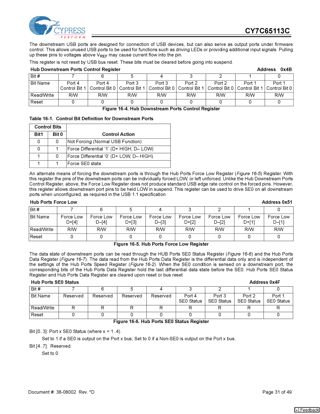
This register is not reset by USB bus reset. These bits must be cleared before going into suspend.
Hub Downstream Ports Control Register |
|
|
|
| Address 0x4B | |||||||
Bit # |
|
| 7 | 6 | 5 | 4 |
| 3 | 2 | 1 | 0 | |
Bit Name |
|
| Port 4 | Port 4 | Port 3 | Port 3 | Port 2 | Port 2 | Port 1 | Port 1 | ||
|
|
| Control Bit 1 | Control Bit 0 | Control Bit 1 | Control Bit 0 | Control Bit 1 | Control Bit 0 | Control Bit 1 | Control Bit 0 | ||
Read/Write |
| R/W | R/W | R/W | R/W | R/W | R/W | R/W | R/W | |||
Reset |
|
| 0 | 0 | 0 | 0 |
| 0 | 0 | 0 | 0 | |
|
|
|
|
| Figure | Downstream Ports Control Register |
|
| ||||
Table |
|
|
|
| ||||||||
|
|
|
|
|
|
|
|
|
|
| ||
Control Bits |
|
|
|
|
|
|
|
|
| |||
Bit1 |
| Bit 0 |
| Control Action |
|
|
|
|
|
| ||
|
|
|
|
|
|
|
|
|
|
| ||
0 |
| 0 |
| Not Forcing (Normal USB Function) |
|
|
|
|
|
| ||
|
|
|
|
|
|
|
|
|
| |||
0 |
| 1 |
| Force Differential ‘1’ (D+ HIGH, D– LOW) |
|
|
|
|
| |||
|
|
|
|
|
|
|
|
|
| |||
1 |
| 0 |
| Force Differential ‘0’ (D+ LOW, D– HIGH) |
|
|
|
|
| |||
|
|
|
|
|
|
|
|
|
|
|
| |
1 |
| 1 |
| Force SE0 state |
|
|
|
|
|
|
| |
|
|
|
|
|
|
|
|
|
|
|
|
|
An alternate means of forcing the downstream ports is through the Hub Ports Force Low Register (Figure
. |
|
|
|
|
|
|
| Address 0x51 | |
Hub Ports Force Low |
|
|
|
|
|
| |||
|
|
|
|
|
|
|
|
|
|
Bit # | 7 | 6 | 5 | 4 | 3 | 2 | 1 |
| 0 |
|
|
|
|
|
|
|
|
|
|
Bit Name | Force Low | Force Low | Force Low | Force Low | Force Low | Force Low | Force Low |
| Force Low |
| D+[4] | D+[3] | D+[2] | D+[1] |
| ||||
Read/Write | R/W | R/W | R/W | R/W | R/W | R/W | R/W |
| R/W |
|
|
|
|
|
|
|
|
|
|
Reset | 0 | 0 | 0 | 0 | 0 | 0 | 0 |
| 0 |
|
|
|
|
|
|
|
|
|
|
|
|
| Figure |
|
|
| |||
The data state of downstream ports can be read through the HUB Ports SE0 Status Register (Figure
.
Hub Ports SE0 Status |
|
|
|
|
|
| Address 0x4F | ||
Bit # | 7 | 6 |
| 5 | 4 | 3 | 2 | 1 | 0 |
Bit Name | Reserved | Reserved |
| Reserved | Reserved | Port 4 | Port 3 | Port 2 | Port 1 |
|
|
|
|
|
| SE0 Status | SE0 Status | SE0 Status | SE0 Status |
Read/Write | R | R |
| R | R | R | R | R | R |
Reset | 0 | 0 |
| 0 | 0 | 0 | 0 | 0 | 0 |
|
|
| Figure |
|
| ||||
Bit [0..3]: Port x SE0 Status (where x = 1..4).
Set to 1 if a SE0 is output on the Port x bus; Set to 0 if a
Bit [4..7]: Reserved.
Set to 0
Document #: | Page 31 of 49 |
[+] Feedback