CY7C65113C
9.1GPIO Configuration Port
Every GPIO port can be programmed as inputs with internal pull-ups, outputs LOW or HIGH, or Hi-Z (floating, the pin is not driven internally). In addition, the interrupt polarity for each port can be programmed. The Port Configuration bits (Figure 9-4) and the Interrupt Enable bit (Figure 9-5through Figure 9-6) determine the interrupt polarity of the port pins
. | | | | | | | | |
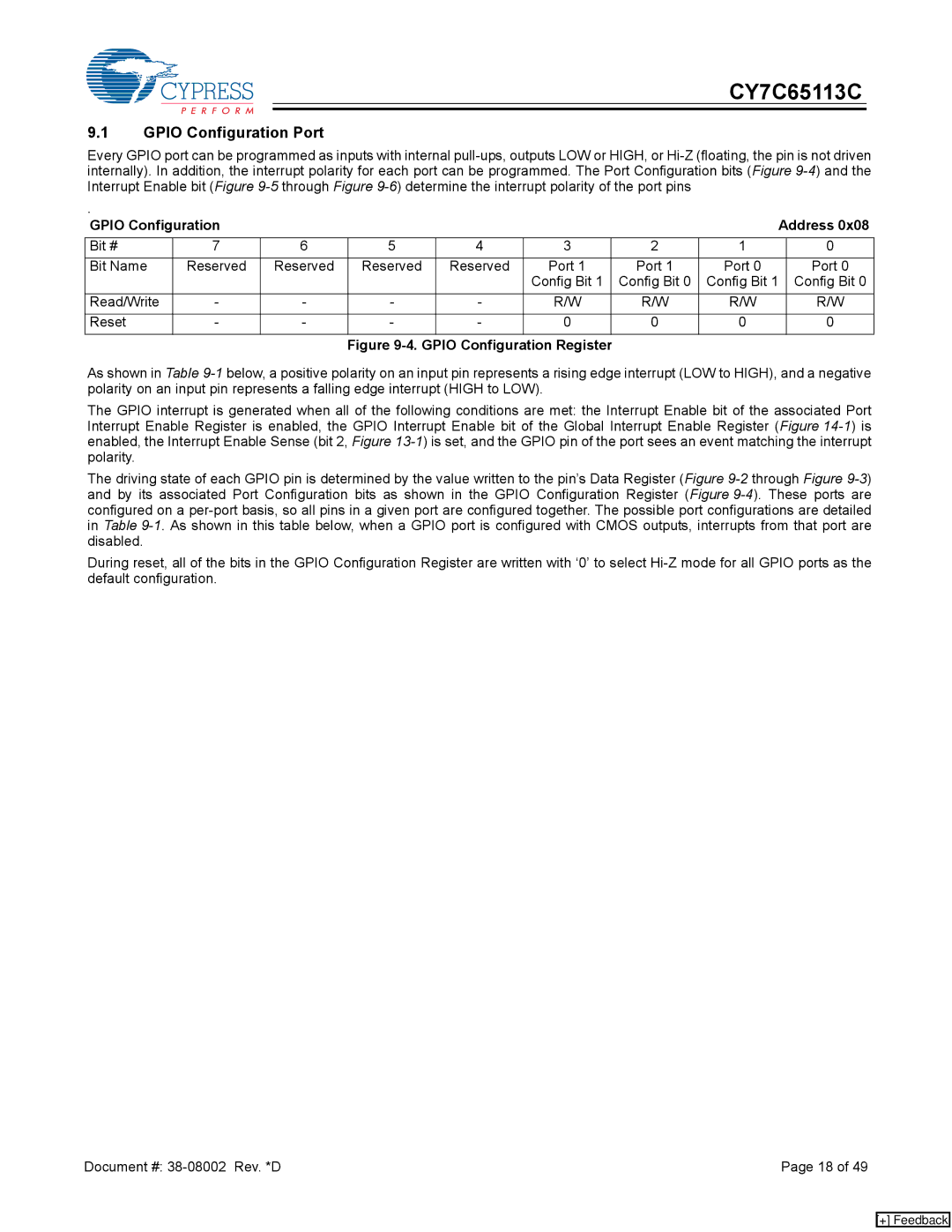
GPIO Configuration | | | | | | Address 0x08 |
Bit # | 7 | 6 | 5 | 4 | 3 | 2 | 1 | 0 |
Bit Name | Reserved | Reserved | Reserved | Reserved | Port 1 | Port 1 | Port 0 | Port 0 |
| | | | | Config Bit 1 | Config Bit 0 | Config Bit 1 | Config Bit 0 |
Read/Write | - | - | - | - | R/W | R/W | R/W | R/W |
Reset | - | - | - | - | 0 | 0 | 0 | 0 |
Figure 9-4. GPIO Configuration Register
As shown in Table 9-1below, a positive polarity on an input pin represents a rising edge interrupt (LOW to HIGH), and a negative polarity on an input pin represents a falling edge interrupt (HIGH to LOW).
The GPIO interrupt is generated when all of the following conditions are met: the Interrupt Enable bit of the associated Port Interrupt Enable Register is enabled, the GPIO Interrupt Enable bit of the Global Interrupt Enable Register (Figure 14-1) is enabled, the Interrupt Enable Sense (bit 2, Figure 13-1) is set, and the GPIO pin of the port sees an event matching the interrupt polarity.
The driving state of each GPIO pin is determined by the value written to the pin’s Data Register (Figure 9-2through Figure 9-3) and by its associated Port Configuration bits as shown in the GPIO Configuration Register (Figure 9-4). These ports are configured on a per-port basis, so all pins in a given port are configured together. The possible port configurations are detailed in Table 9-1. As shown in this table below, when a GPIO port is configured with CMOS outputs, interrupts from that port are disabled.
During reset, all of the bits in the GPIO Configuration Register are written with ‘0’ to select Hi-Z mode for all GPIO ports as the default configuration.
Document #: 38-08002 Rev. *D | Page 18 of 49 |
[+] Feedback