CY7C65113C
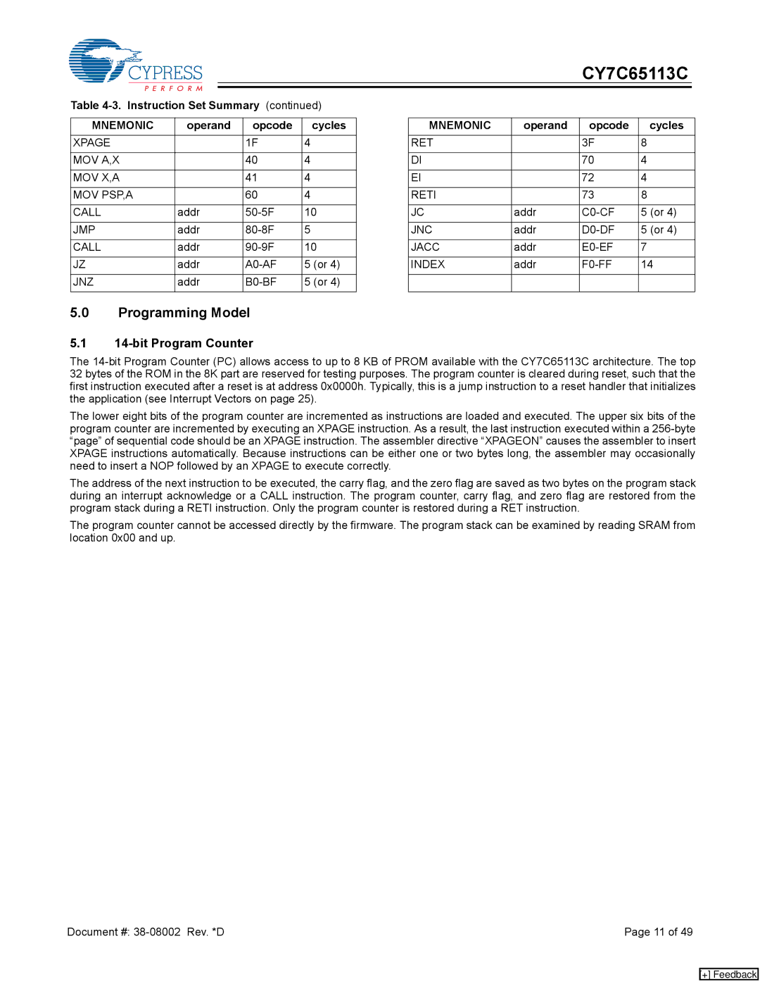
Table 4-3. Instruction Set Summary (continued)
MNEMONIC | operand | opcode | cycles |
XPAGE |
| 1F | 4 |
|
|
|
|
MOV A,X |
| 40 | 4 |
|
|
|
|
MOV X,A |
| 41 | 4 |
|
|
|
|
MOV PSP,A |
| 60 | 4 |
|
|
|
|
CALL | addr | 10 | |
|
|
|
|
JMP | addr | 5 | |
|
|
|
|
CALL | addr | 10 | |
|
|
|
|
JZ | addr | 5 (or 4) | |
|
|
|
|
JNZ | addr | 5 (or 4) | |
|
|
|
|
MNEMONIC | operand | opcode | cycles |
RET |
| 3F | 8 |
|
|
|
|
DI |
| 70 | 4 |
|
|
|
|
EI |
| 72 | 4 |
|
|
|
|
RETI |
| 73 | 8 |
|
|
|
|
JC | addr | 5 (or 4) | |
|
|
|
|
JNC | addr | 5 (or 4) | |
|
|
|
|
JACC | addr | 7 | |
|
|
|
|
INDEX | addr | 14 | |
|
|
|
|
|
|
|
|
5.0Programming Model
5.114-bit Program Counter
The
The lower eight bits of the program counter are incremented as instructions are loaded and executed. The upper six bits of the program counter are incremented by executing an XPAGE instruction. As a result, the last instruction executed within a
The address of the next instruction to be executed, the carry flag, and the zero flag are saved as two bytes on the program stack during an interrupt acknowledge or a CALL instruction. The program counter, carry flag, and zero flag are restored from the program stack during a RETI instruction. Only the program counter is restored during a RET instruction.
The program counter cannot be accessed directly by the firmware. The program stack can be examined by reading SRAM from location 0x00 and up.
Document #: | Page 11 of 49 |
[+] Feedback