CY7C65113C
6.The host sends a request for the Device descriptor using the new USB address.
7.Firmware decodes the request and retrieves the Device descriptor from program memory tables.
8.The host performs a control read sequence and Firmware responds by sending its Device descriptor over the USB bus.
9.The host generates control reads from the device to request the Configuration and Report descriptors.
10.Once the device receives a Set Configuration request, its functions may now be used.
11.Following enumeration as a hub, Firmware can optionally indicate to the host that a compound device exists (for example, the keyboard in a keyboard/hub device).
12.The host carries out the enumeration process with this additional function as though it were attached downstream from the hub. 13.When the host assigns an address to this device, it is stored as the other USB address (for example, Address A).
16.0USB Hub
A USB hub is required to support:
•Connectivity behavior: service connect/disconnect detection
•Bus fault detection and recovery
•
These features are mapped onto a hub repeater and a hub controller. The hub controller is supported by the processor integrated into the CY7C65113C microcontroller. The hardware in the hub repeater detects whether a USB device is connected to a downstream port. The connection to a downstream port is through a differential signal pair (D+ and
The hub must have a resistor RUUP connected between its upstream D+ line and VREG to indicate it is a full speed USB device.
The hub generates an EOP at EOF1, in accordance with the USB 1.1 Specification (section 11.2.2, page 234) as well as USB 2.0 specification (section 11.2.5, page 304).
16.1Connecting/Disconnecting a USB Device
A
A
Connects are recorded by the time a
When a USB device is disconnected from the Hub, the downstream signal pair eventually floats to a
. |
|
|
|
|
|
|
|
| Address 0x48 | |
Hub Ports Connect Status |
|
|
|
|
|
| ||||
Bit # | 7 |
| 6 | 5 | 4 | 3 | 2 | 1 |
| 0 |
Bit Name | Reserved |
| Reserved | Reserved | Reserved | Port 4 | Port 3 | Port 2 |
| Port 1 |
|
|
|
|
|
| Connect | Connect | Connect |
| Connect |
|
|
|
|
|
| Status | Status | Status |
| Status |
Read/Write | R/W |
| R/W | R/W | R/W | R/W | R/W | R/W |
| R/W |
Reset | 0 |
| 0 | 0 | 0 | 0 | 0 | 0 |
| 0 |
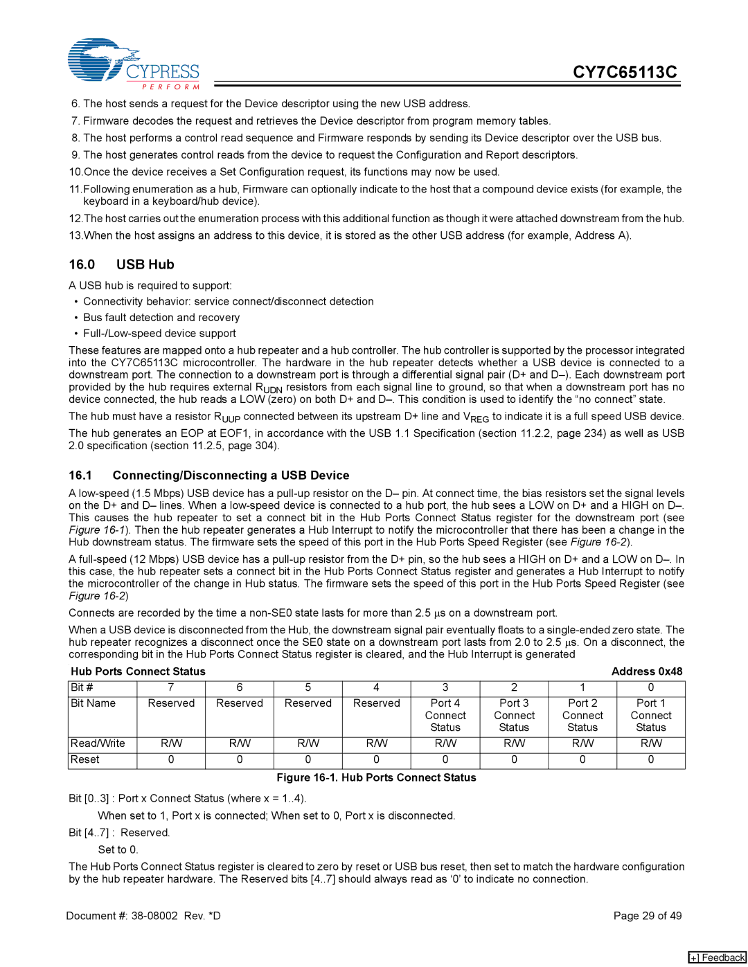
Figure 16-1. Hub Ports Connect Status
Bit [0..3] : Port x Connect Status (where x = 1..4).
When set to 1, Port x is connected; When set to 0, Port x is disconnected. Bit [4..7] : Reserved.
Set to 0.
The Hub Ports Connect Status register is cleared to zero by reset or USB bus reset, then set to match the hardware configuration by the hub repeater hardware. The Reserved bits [4..7] should always read as ‘0’ to indicate no connection.
Document #: | Page 29 of 49 |
[+] Feedback