CY7C65113C
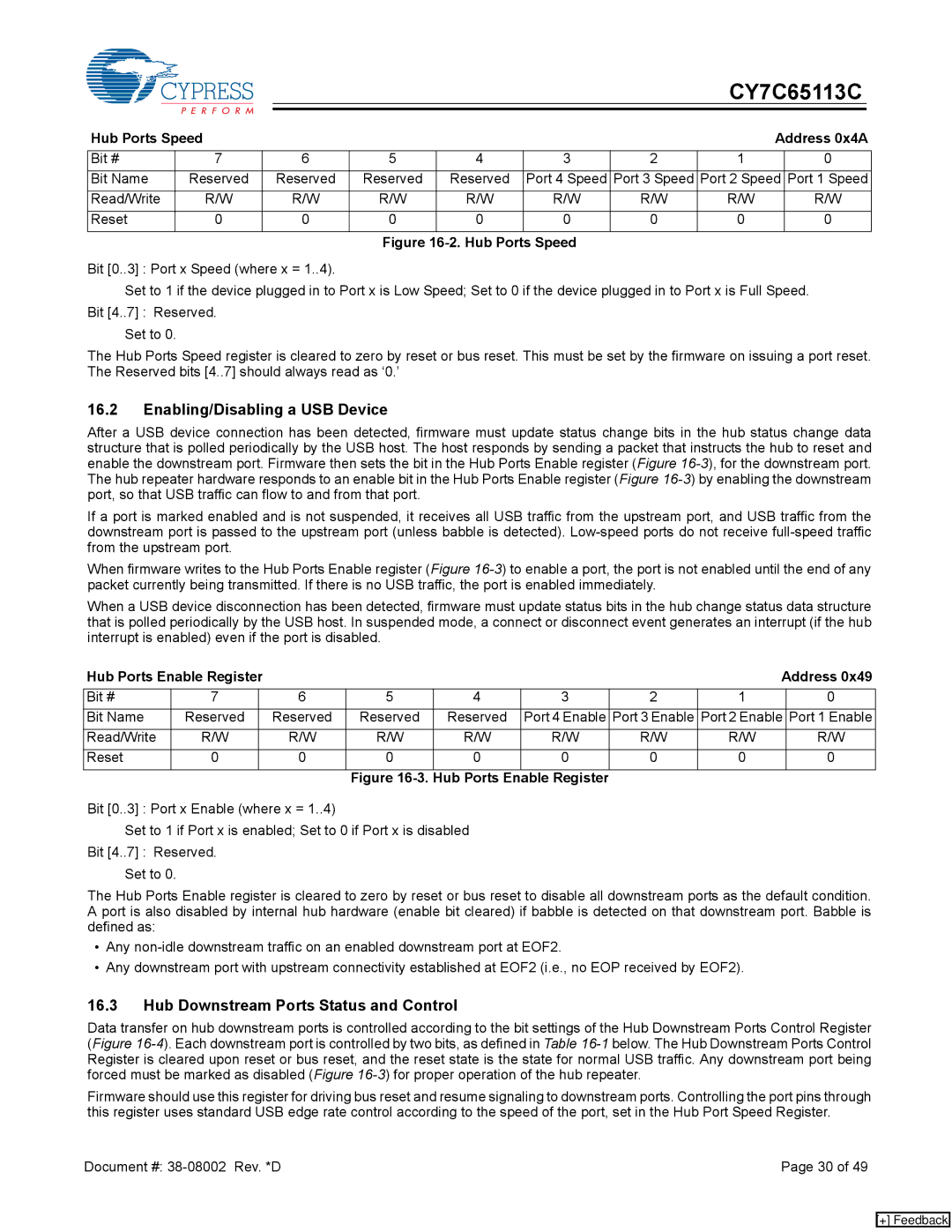
Hub Ports Speed |
|
|
|
|
|
| Address 0x4A | ||
Bit # | 7 | 6 | 5 | 4 | 3 | 2 | 1 |
| 0 |
Bit Name | Reserved | Reserved | Reserved | Reserved | Port 4 Speed | Port 3 Speed | Port 2 Speed | Port 1 Speed | |
Read/Write | R/W | R/W | R/W | R/W | R/W | R/W | R/W |
| R/W |
Reset | 0 | 0 | 0 | 0 | 0 | 0 | 0 |
| 0 |
Figure 16-2. Hub Ports Speed
Bit [0..3] : Port x Speed (where x = 1..4).
Set to 1 if the device plugged in to Port x is Low Speed; Set to 0 if the device plugged in to Port x is Full Speed. Bit [4..7] : Reserved.
Set to 0.
The Hub Ports Speed register is cleared to zero by reset or bus reset. This must be set by the firmware on issuing a port reset. The Reserved bits [4..7] should always read as ‘0.’
16.2Enabling/Disabling a USB Device
After a USB device connection has been detected, firmware must update status change bits in the hub status change data structure that is polled periodically by the USB host. The host responds by sending a packet that instructs the hub to reset and enable the downstream port. Firmware then sets the bit in the Hub Ports Enable register (Figure
If a port is marked enabled and is not suspended, it receives all USB traffic from the upstream port, and USB traffic from the downstream port is passed to the upstream port (unless babble is detected).
When firmware writes to the Hub Ports Enable register (Figure
When a USB device disconnection has been detected, firmware must update status bits in the hub change status data structure that is polled periodically by the USB host. In suspended mode, a connect or disconnect event generates an interrupt (if the hub interrupt is enabled) even if the port is disabled.
Hub Ports Enable Register |
|
|
|
|
|
| Address 0x49 | |||
Bit # | 7 |
| 6 | 5 | 4 | 3 | 2 | 1 |
| 0 |
Bit Name | Reserved |
| Reserved | Reserved | Reserved | Port 4 Enable | Port 3 Enable | Port 2 Enable | Port 1 Enable | |
Read/Write | R/W |
| R/W | R/W | R/W | R/W | R/W | R/W |
| R/W |
Reset | 0 |
| 0 | 0 | 0 | 0 | 0 | 0 |
| 0 |
|
|
|
| Figure | Hub Ports Enable Register |
|
|
|
| |
Bit [0..3] : Port x Enable (where x = 1..4)
Set to 1 if Port x is enabled; Set to 0 if Port x is disabled Bit [4..7] : Reserved.
Set to 0.
The Hub Ports Enable register is cleared to zero by reset or bus reset to disable all downstream ports as the default condition. A port is also disabled by internal hub hardware (enable bit cleared) if babble is detected on that downstream port. Babble is defined as:
•Any
•Any downstream port with upstream connectivity established at EOF2 (i.e., no EOP received by EOF2).
16.3Hub Downstream Ports Status and Control
Data transfer on hub downstream ports is controlled according to the bit settings of the Hub Downstream Ports Control Register (Figure
Firmware should use this register for driving bus reset and resume signaling to downstream ports. Controlling the port pins through this register uses standard USB edge rate control according to the speed of the port, set in the Hub Port Speed Register.
Document #: | Page 30 of 49 |
[+] Feedback