CY7C65113C
13.0Processor Status and Control Register
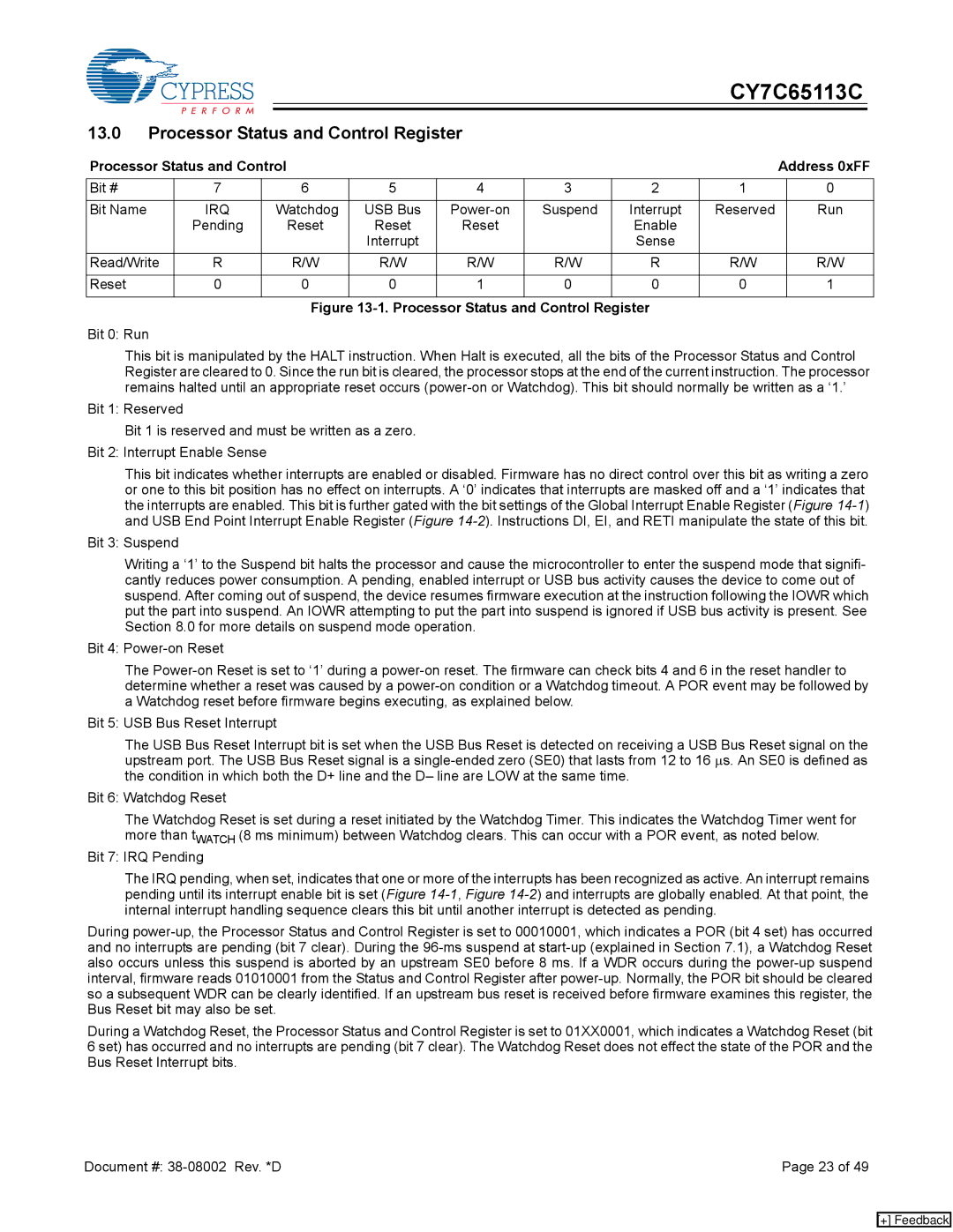
Processor Status and Control |
|
|
|
|
| Address 0xFF | |||
Bit # | 7 | 6 | 5 | 4 | 3 | 2 | 1 |
| 0 |
|
|
|
|
|
|
|
|
|
|
Bit Name | IRQ | Watchdog | USB Bus | Suspend | Interrupt | Reserved |
| Run | |
| Pending | Reset | Reset | Reset |
| Enable |
|
|
|
|
|
| Interrupt |
|
| Sense |
|
|
|
Read/Write | R | R/W | R/W | R/W | R/W | R | R/W |
| R/W |
|
|
|
|
|
|
|
|
|
|
Reset | 0 | 0 | 0 | 1 | 0 | 0 | 0 |
| 1 |
|
|
|
|
|
|
|
|
|
|
Figure 13-1. Processor Status and Control Register
Bit 0: Run
This bit is manipulated by the HALT instruction. When Halt is executed, all the bits of the Processor Status and Control Register are cleared to 0. Since the run bit is cleared, the processor stops at the end of the current instruction. The processor remains halted until an appropriate reset occurs
Bit 1: Reserved
Bit 1 is reserved and must be written as a zero. Bit 2: Interrupt Enable Sense
This bit indicates whether interrupts are enabled or disabled. Firmware has no direct control over this bit as writing a zero or one to this bit position has no effect on interrupts. A ‘0’ indicates that interrupts are masked off and a ‘1’ indicates that the interrupts are enabled. This bit is further gated with the bit settings of the Global Interrupt Enable Register (Figure
Bit 3: Suspend
Writing a ‘1’ to the Suspend bit halts the processor and cause the microcontroller to enter the suspend mode that signifi- cantly reduces power consumption. A pending, enabled interrupt or USB bus activity causes the device to come out of suspend. After coming out of suspend, the device resumes firmware execution at the instruction following the IOWR which put the part into suspend. An IOWR attempting to put the part into suspend is ignored if USB bus activity is present. See Section 8.0 for more details on suspend mode operation.
Bit 4:
The
Bit 5: USB Bus Reset Interrupt
The USB Bus Reset Interrupt bit is set when the USB Bus Reset is detected on receiving a USB Bus Reset signal on the upstream port. The USB Bus Reset signal is a
Bit 6: Watchdog Reset
The Watchdog Reset is set during a reset initiated by the Watchdog Timer. This indicates the Watchdog Timer went for more than tWATCH (8 ms minimum) between Watchdog clears. This can occur with a POR event, as noted below.
Bit 7: IRQ Pending
The IRQ pending, when set, indicates that one or more of the interrupts has been recognized as active. An interrupt remains pending until its interrupt enable bit is set (Figure
During
During a Watchdog Reset, the Processor Status and Control Register is set to 01XX0001, which indicates a Watchdog Reset (bit 6 set) has occurred and no interrupts are pending (bit 7 clear). The Watchdog Reset does not effect the state of the POR and the Bus Reset Interrupt bits.
Document #: | Page 23 of 49 |
[+] Feedback