|
|
|
|
|
|
|
| CY7C65113C |
|
|
|
|
|
|
|
|
|
|
|
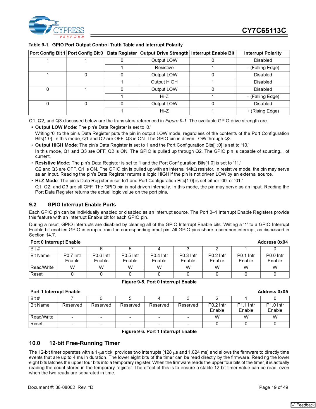
Table |
|
|
| ||||||
|
|
|
|
|
|
| |||
Port Config Bit 1 | Port Config Bit 0 | Data Register | Output Drive Strength | Interrupt Enable Bit | Interrupt Polarity |
| |||
|
|
|
|
|
|
|
|
| |
1 |
| 1 |
| 0 | Output LOW | 0 | Disabled |
| |
|
|
|
|
|
|
|
|
|
|
|
|
|
|
| 1 | Resistive | 1 | – (Falling Edge) |
|
|
|
|
|
|
|
|
|
| |
1 |
| 0 |
| 0 | Output LOW | 0 | Disabled |
| |
|
|
|
|
|
|
|
|
|
|
|
|
|
|
| 1 | Output HIGH | 1 | Disabled |
|
|
|
|
|
|
|
|
|
| |
0 |
| 1 |
| 0 | Output LOW | 0 | Disabled |
| |
|
|
|
|
|
|
|
|
|
|
|
|
|
|
| 1 | 1 | – (Falling Edge) |
| |
|
|
|
|
|
|
|
|
| |
0 |
| 0 |
| 0 | Output LOW | 0 | Disabled |
| |
|
|
|
|
|
|
|
|
|
|
|
|
|
|
| 1 | 1 | + (Rising Edge) |
| |
|
|
|
|
|
|
|
|
|
|
Q1, Q2, and Q3 discussed below are the transistors referenced in Figure
•Output LOW Mode: The pin’s Data Register is set to ‘0.’
Writing ‘0’ to the pin’s Data Register puts the pin in output LOW mode, regardless of the contents of the Port Configuration Bits[1:0]. In this mode, Q1 and Q2 are OFF. Q3 is ON. The GPIO pin is driven LOW through Q3.
•Output HIGH Mode: The pin’s Data Register is set to 1 and the Port Configuration Bits[1:0] is set to ‘10.’
In this mode, Q1 and Q3 are OFF. Q2 is ON. The GPIO is pulled up through Q2. The GPIO pin is capable of sourcing... of current.
•Resistive Mode: The pin’s Data Register is set to 1 and the Port Configuration Bits[1:0] is set to ‘11.’
Q2 and Q3 are OFF. Q1 is ON. The GPIO pin is pulled up with an internal 14kΩ resistor. In resistive mode, the pin may serve as an input. Reading the pin’s Data Register returns a logic HIGH if the pin is not driven LOW by an external source.
•
Q1, Q2, and Q3 are all OFF. The GPIO pin is not driven internally. In this mode, the pin may serve as an input. Reading the Port Data Register returns the actual logic value on the port pins.
9.2GPIO Interrupt Enable Ports
Each GPIO pin can be individually enabled or disabled as an interrupt source. The Port
During a reset, GPIO interrupts are disabled by clearing all of the GPIO Interrupt Enable bits. Writing a ‘1’ to a GPIO Interrupt Enable bit enables GPIO interrupts from the corresponding input pin. All GPIO pins share a common interrupt, as discussed in Section 14.7.
. |
|
|
|
|
|
|
|
| Address 0x04 | |
Port 0 Interrupt Enable |
|
|
|
|
|
|
| |||
Bit # | 7 | 6 |
| 5 | 4 | 3 | 2 | 1 |
| 0 |
Bit Name | P0.7 Intr | P0.6 | Intr | P0.5 Intr | P0.4 Intr | P0.3 Intr | P0.2 Intr | P0.1 Intr |
| P0.0 Intr |
| Enable | Enable | Enable | Enable | Enable | Enable | Enable |
| Enable | |
Read/Write | W | W | W | W | W | W | W |
| W | |
Reset | 0 | 0 |
| 0 | 0 | 0 | 0 | 0 |
| 0 |
|
|
|
| Figure |
|
|
|
| ||
Port 1 Interrupt Enable |
|
|
|
|
|
|
| Address 0x05 | ||
|
|
|
|
|
|
|
|
|
|
|
Bit # | 7 | 6 |
| 5 | 4 | 3 | 2 | 1 |
| 0 |
Bit Name | Reserved | Reserved | Reserved | Reserved | Reserved | P0.2 Intr | P1.1 Intr |
| P1.0 Intr | |
|
|
|
|
|
|
| Enable | Enable |
| Enable |
Read/Write | - | - |
| - | - | - | W | W |
| W |
Reset | - | - |
| - | - | - | 0 | 0 |
| 0 |
Figure 9-6. Port 1 Interrupt Enable
10.012-bit Free-Running Timer
The
Document #: | Page 19 of 49 |
[+] Feedback