CY7C65113C
Bits[6:0] of the endpoint 0 mode register are locked from CPU write operations whenever the SIE has updated one of these bits, which the SIE does only at the end of the token phase of a transaction (SETUP... Data... ACK, OUT... Data... ACK, or IN... Data...
ACK). The CPU can unlock these bits by doing a subsequent read of this register. Only endpoint 0 mode registers are locked when updated. The locking mechanism does not apply to the mode registers of other endpoints.
Because of these hardware locking features, firmware must perform an IORD after an IOWR to an endpoint 0 register. This verifies that the contents have changed as desired, and that the SIE has not updated these values.
While the SETUP bit is set, the CPU cannot write to the endpoint zero FIFOs. This prevents firmware from overwriting an incoming SETUP transaction before firmware has a chance to read the SETUP data. Refer to Table
The Mode bits (bits [3:0]) control how the endpoint responds to USB bus traffic. The mode bit encoding is shown in Table
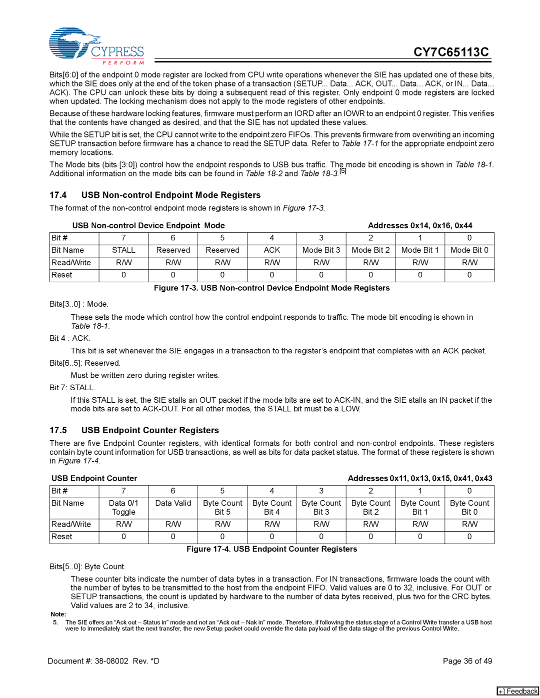
17.4USB Non-control Endpoint Mode Registers
The format of the
USB |
|
| Addresses 0x14, 0x16, 0x44 | |||||
Bit # | 7 | 6 | 5 | 4 | 3 | 2 | 1 | 0 |
|
|
|
|
|
|
|
|
|
Bit Name | STALL | Reserved | Reserved | ACK | Mode Bit 3 | Mode Bit 2 | Mode Bit 1 | Mode Bit 0 |
|
|
|
|
|
|
|
|
|
Read/Write | R/W | R/W | R/W | R/W | R/W | R/W | R/W | R/W |
|
|
|
|
|
|
|
|
|
Reset | 0 | 0 | 0 | 0 | 0 | 0 | 0 | 0 |
|
|
|
|
|
|
|
|
|
Figure 17-3. USB Non-control Device Endpoint Mode Registers
Bits[3..0] : Mode.
These sets the mode which control how the control endpoint responds to traffic. The mode bit encoding is shown in Table
Bit 4 : ACK.
This bit is set whenever the SIE engages in a transaction to the register’s endpoint that completes with an ACK packet. Bits[6..5]: Reserved.
Must be written zero during register writes. Bit 7: STALL.
If this STALL is set, the SIE stalls an OUT packet if the mode bits are set to
17.5USB Endpoint Counter Registers
There are five Endpoint Counter registers, with identical formats for both control and
USB Endpoint Counter |
|
|
|
| Addresses 0x11, 0x13, 0x15, 0x41, 0x43 | |||
Bit # | 7 | 6 | 5 | 4 | 3 | 2 | 1 | 0 |
|
|
|
|
|
|
|
|
|
Bit Name | Data 0/1 | Data Valid | Byte Count | Byte Count | Byte Count | Byte Count | Byte Count | Byte Count |
| Toggle |
| Bit 5 | Bit 4 | Bit 3 | Bit 2 | Bit 1 | Bit 0 |
Read/Write | R/W | R/W | R/W | R/W | R/W | R/W | R/W | R/W |
|
|
|
|
|
|
|
|
|
Reset | 0 | 0 | 0 | 0 | 0 | 0 | 0 | 0 |
|
|
|
|
|
|
|
|
|
Figure 17-4. USB Endpoint Counter Registers
Bits[5..0]: Byte Count.
These counter bits indicate the number of data bytes in a transaction. For IN transactions, firmware loads the count with the number of bytes to be transmitted to the host from the endpoint FIFO. Valid values are 0 to 32, inclusive. For OUT or SETUP transactions, the count is updated by hardware to the number of data bytes received, plus two for the CRC bytes. Valid values are 2 to 34, inclusive.
Note:
5.The SIE offers an “Ack out – Status in” mode and not an “Ack out – Nak in” mode. Therefore, if following the status stage of a Control Write transfer a USB host were to immediately start the next transfer, the new Setup packet could override the data payload of the data stage of the previous Control Write.
Document #: | Page 36 of 49 |
[+] Feedback