CY7C65113C
Table
Control Bits | Control Action |
000 | Not Forcing (SIE Controls Driver) |
|
|
001 | Force D+[0] HIGH, |
|
|
010 | Force D+[0] LOW, |
|
|
011 | Force SE0; D+[0] LOW, |
|
|
100 | Force D+[0] LOW, |
|
|
101 | Force D+[0] HiZ, |
|
|
110 | Force D+[0] LOW, |
|
|
111 | Force D+[0] HiZ, |
|
|
Bit 3: Bus Activity.
This is a “sticky” bit that indicates if any
Bits 4 and 5: D– Upstream and D+ Upstream.
These bits give the state of each upstream port pin individually: 1 = HIGH, 0 = LOW.
Bit 6: Endpoint Mode.
This bit used to configure the number of USB endpoints. See Section 17.2 for a detailed description.
Bit 7: Endpoint Size.
This bit used to configure the number of USB endpoints. See Section 17.2 for a detailed description.
The hub generates an EOP at EOF1 in accordance with the USB 1.1 Specification, Section 11.2.2 as well as USB 2.0 specification (section 11.2.5, page 304).
17.0USB Serial Interface Engine Operation
The CY7C65113C SIE supports operation as a single device or a compound device. This section describes the two device addresses, the configurable endpoints, and the endpoint function.
17.1USB Device Addresses
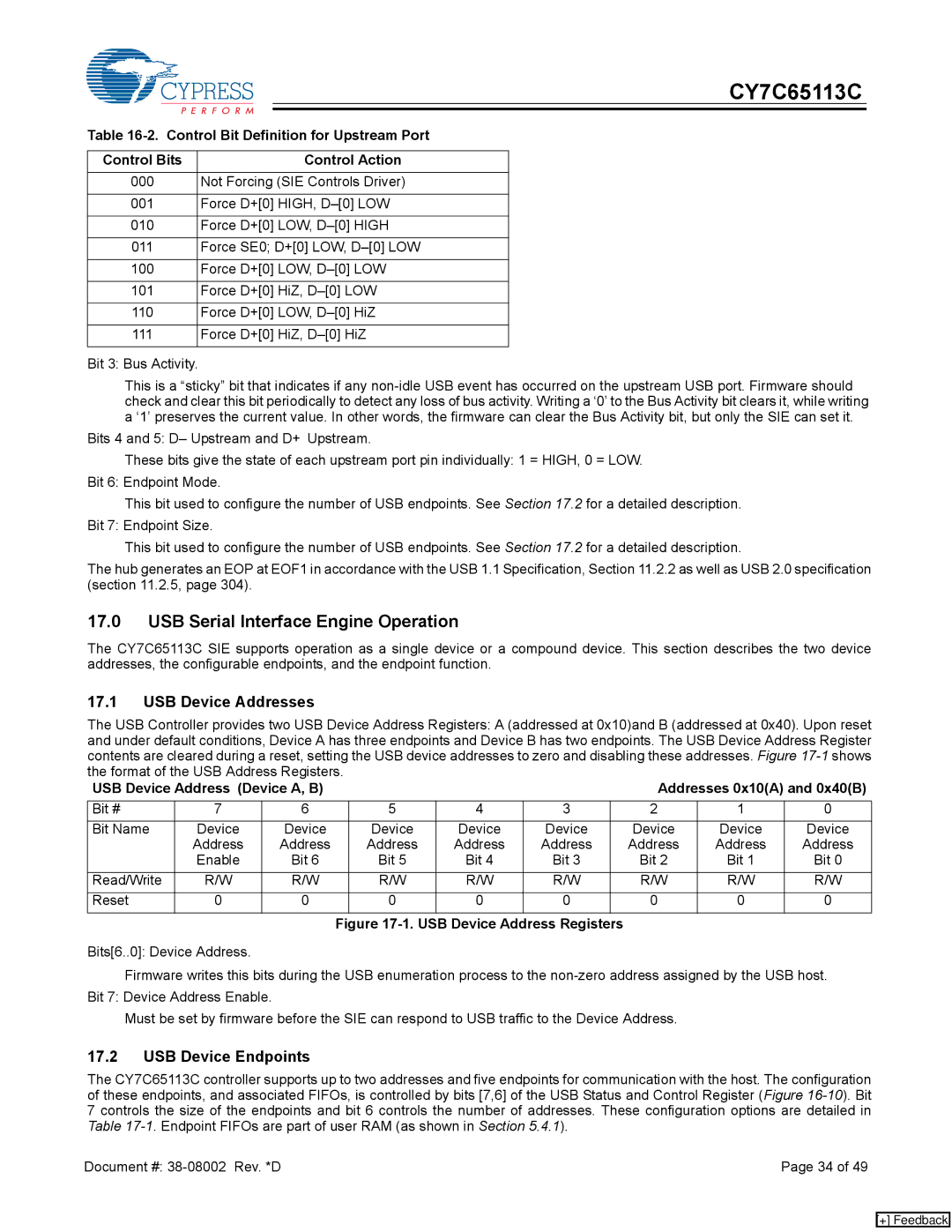
The USB Controller provides two USB Device Address Registers: A (addressed at 0x10)and B (addressed at 0x40). Upon reset and under default conditions, Device A has three endpoints and Device B has two endpoints. The USB Device Address Register contents are cleared during a reset, setting the USB device addresses to zero and disabling these addresses. Figure
USB Device Address (Device A, B) |
|
|
| Addresses 0x10(A) and 0x40(B) | ||||
Bit # | 7 | 6 | 5 | 4 | 3 | 2 | 1 | 0 |
Bit Name | Device | Device | Device | Device | Device | Device | Device | Device |
| Address | Address | Address | Address | Address | Address | Address | Address |
| Enable | Bit 6 | Bit 5 | Bit 4 | Bit 3 | Bit 2 | Bit 1 | Bit 0 |
Read/Write | R/W | R/W | R/W | R/W | R/W | R/W | R/W | R/W |
Reset | 0 | 0 | 0 | 0 | 0 | 0 | 0 | 0 |
Figure 17-1. USB Device Address Registers
Bits[6..0]: Device Address.
Firmware writes this bits during the USB enumeration process to the
Must be set by firmware before the SIE can respond to USB traffic to the Device Address.
17.2USB Device Endpoints
The CY7C65113C controller supports up to two addresses and five endpoints for communication with the host. The configuration of these endpoints, and associated FIFOs, is controlled by bits [7,6] of the USB Status and Control Register (Figure
Document #: | Page 34 of 49 |
[+] Feedback