CY7C65113C
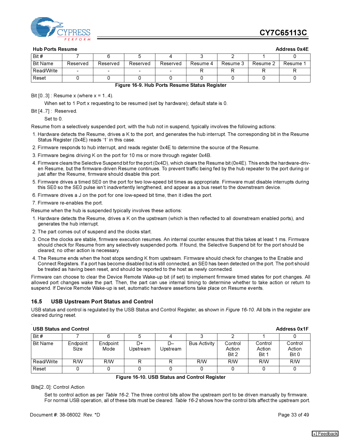
Hub Ports Resume |
|
|
|
|
|
| Address 0x4E | ||
Bit # | 7 | 6 | 5 | 4 | 3 | 2 | 1 |
| 0 |
Bit Name | Reserved | Reserved | Reserved | Reserved | Resume 4 | Resume 3 | Resume 2 |
| Resume 1 |
Read/Write | - | - | - | - | R | R | R |
| R |
Reset | 0 | 0 | 0 | 0 | 0 | 0 | 0 |
| 0 |
|
| Figure |
|
|
| ||||
Bit [0..3] : Resume x (where x = 1..4).
When set to 1 Port x requesting to be resumed (set by hardware); default state is 0. Bit [4..7] : Reserved.
Set to 0.
Resume from a selectively suspended port, with the hub not in suspend, typically involves the following actions:
1.Hardware detects the Resume, drives a K to the port, and generates the hub interrupt. The corresponding bit in the Resume Status Register (0x4E) reads ‘1’ in this case.
2.Firmware responds to hub interrupt, and reads register 0x4E to determine the source of the Resume.
3.Firmware begins driving K on the port for 10 ms or more through register 0x4B.
4.Firmware clears the Selective Suspend bit for the port (0x4D), which clears the Resume bit (0x4E). This ends the
5.Firmware drives a timed SE0 on the port for two
6.Firmware drives a J on the port for one
7.Firmware
Resume when the hub is suspended typically involves these actions:
1.Hardware detects the Resume, drives a K on the upstream (which is then reflected to all downstream enabled ports), and generates the hub interrupt.
2.The part comes out of suspend and the clocks start.
3.Once the clocks are stable, firmware execution resumes. An internal counter ensures that this takes at least 1 ms. Firmware should check for Resume from any selectively suspended ports. If found, the Selective Suspend bit for the port should be cleared; no other action is necessary.
4.The Resume ends when the host stops sending K from upstream. Firmware should check for changes to the Enable and Connect Registers. If a port has become disabled but is still connected, an SE0 has been detected on the port. The port should be treated as having been reset, and should be reported to the host as newly connected.
Firmware can choose to clear the Device Remote
16.5USB Upstream Port Status and Control
USB status and control is regulated by the USB Status and Control Register, as shown in Figure
. |
|
|
|
|
|
|
|
|
|
USB Status and Control |
|
|
|
|
|
| Address 0x1F | ||
Bit # | 7 | 6 | 5 | 4 | 3 | 2 | 1 |
| 0 |
Bit Name | Endpoint | Endpoint | D+ | D– | Bus Activity | Control | Control |
| Control |
| Size | Mode | Upstream | Upstream |
| Action | Action |
| Action |
|
|
|
|
|
| Bit 2 | Bit 1 |
| Bit 0 |
Read/Write | R/W | R/W | R | R | R/W | R/W | R/W |
| R/W |
Reset | 0 | 0 | 0 | 0 | 0 | 0 | 0 |
| 0 |
Figure 16-10. USB Status and Control Register
Bits[2..0]: Control Action
Set to control action as per Table
Document #: | Page 33 of 49 |
[+] Feedback