CY7C65113C
Comments
Some Mode Bits are automatically changed by the SIE in response to certain USB transactions. For example, if the Mode Bits [3:0] are set to '1111' which is ACK
Any SETUP packet to an enabled endpoint with mode set to accept SETUPs will be changed by the SIE to 0001 (NAKing INs and OUTs). Any mode set to accept a SETUP will send an ACK handshake to a valid SETUP token.
The control endpoint has three status bits for identifying the token type received (SETUP, IN, or OUT), but the endpoint must be placed in the correct mode to function as such.
.
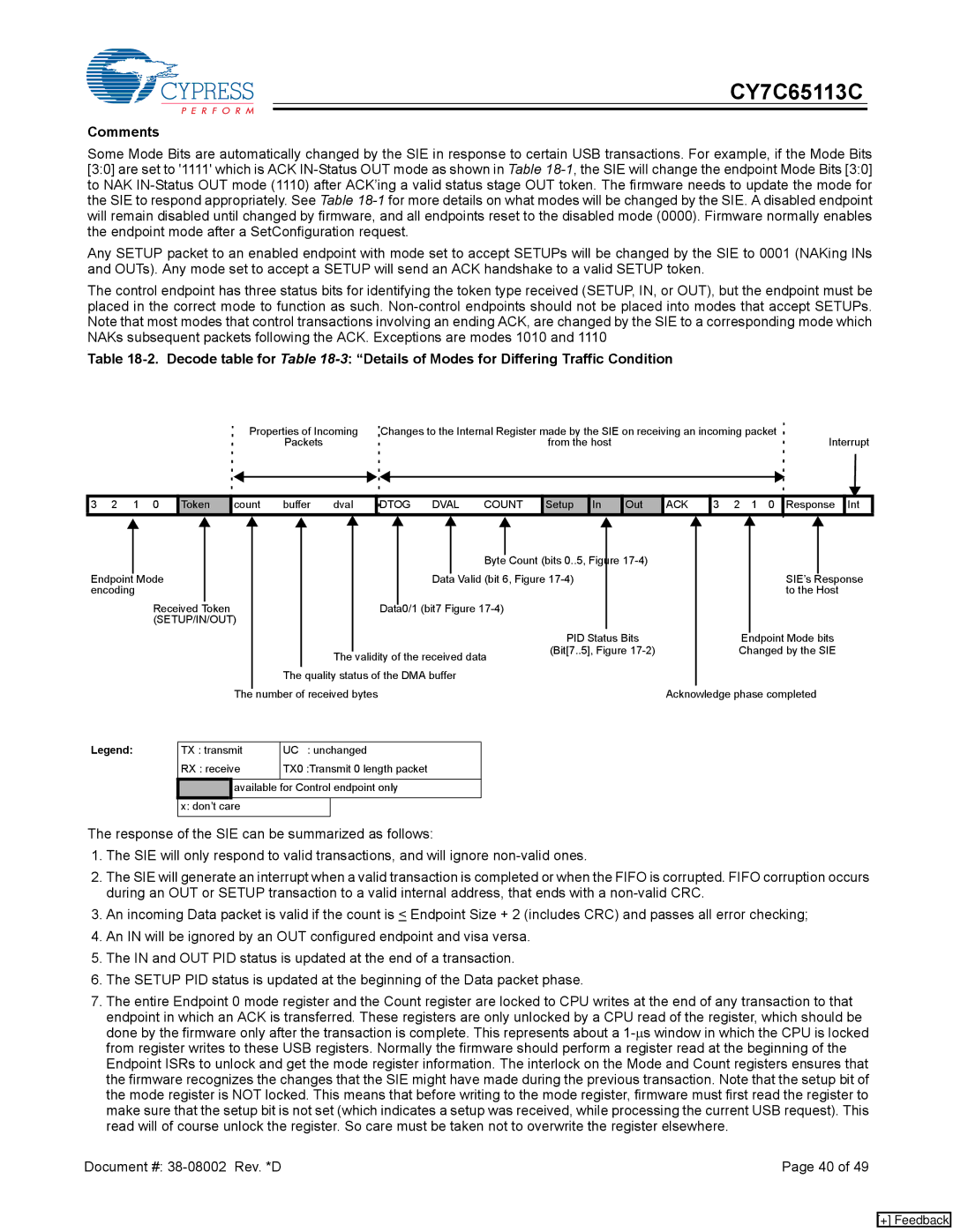
Table
Properties of Incoming | Changes to the Internal Register made by the SIE on receiving an incoming packet | Interrupt |
Packets | from the host |
3 | 2 | 1 | 0 | Token | count | buffer | dval | DTOG | DVAL | COUNT | Setup | In | Out | ACK | 3 | 2 | 1 | 0 | Response | Int |
|
|
|
|
|
|
|
|
|
|
|
| Byte |
| Count (bits 0..5, Figure |
|
|
|
|
|
|
|
|
|
|
|
|
|
|
|
|
|
|
|
|
|
|
| ||
|
|
|
|
|
|
|
|
|
|
|
|
|
|
|
|
|
| ||
Endpoint |
| Mode |
|
|
|
| Data |
| Valid (bit 6, Figure |
|
| SIE’s |
| Response | |||||
|
|
|
|
|
|
| |||||||||||||
encoding |
|
|
|
|
|
|
|
|
|
|
|
|
|
| to the Host | ||||
|
|
| Received | Token |
|
| Data0/1 (bit7 Figure |
|
|
|
|
|
|
| |||||
|
|
| (SETUP/IN/OUT) |
|
|
|
|
|
|
|
|
|
|
|
|
|
| ||
|
|
|
|
|
|
|
|
|
|
|
|
|
| PID Status Bits |
|
| Endpoint Mode bits | ||
|
|
|
|
|
|
|
|
|
|
|
|
|
| (Bit[7..5], Figure |
| Changed by the SIE | |||
|
|
|
|
|
|
| The validity of the received data | ||||||||||||
|
|
|
|
|
|
|
|
|
|
|
|
|
| ||||||
|
|
|
|
|
| The quality status of the DMA buffer |
|
|
|
|
|
|
| ||||||
Legend: |
|
| The | number of received bytes |
|
| Acknowledge phase completed | ||||||||||||
|
|
|
|
|
|
|
|
|
|
|
|
|
|
|
|
| |||
| TX : transmit | UC : unchanged |
|
|
|
|
|
|
| ||||||||||
|
|
|
| RX : receive | TX0 :Transmit 0 length packet |
|
|
|
|
|
|
| |||||||
![]()
![]() available for Control endpoint only x: don’t care
available for Control endpoint only x: don’t care
The response of the SIE can be summarized as follows:
1.The SIE will only respond to valid transactions, and will ignore
2.The SIE will generate an interrupt when a valid transaction is completed or when the FIFO is corrupted. FIFO corruption occurs during an OUT or SETUP transaction to a valid internal address, that ends with a
3.An incoming Data packet is valid if the count is < Endpoint Size + 2 (includes CRC) and passes all error checking;
4.An IN will be ignored by an OUT configured endpoint and visa versa.
5.The IN and OUT PID status is updated at the end of a transaction.
6.The SETUP PID status is updated at the beginning of the Data packet phase.
7.The entire Endpoint 0 mode register and the Count register are locked to CPU writes at the end of any transaction to that endpoint in which an ACK is transferred. These registers are only unlocked by a CPU read of the register, which should be done by the firmware only after the transaction is complete. This represents about a
Document #: | Page 40 of 49 |
[+] Feedback