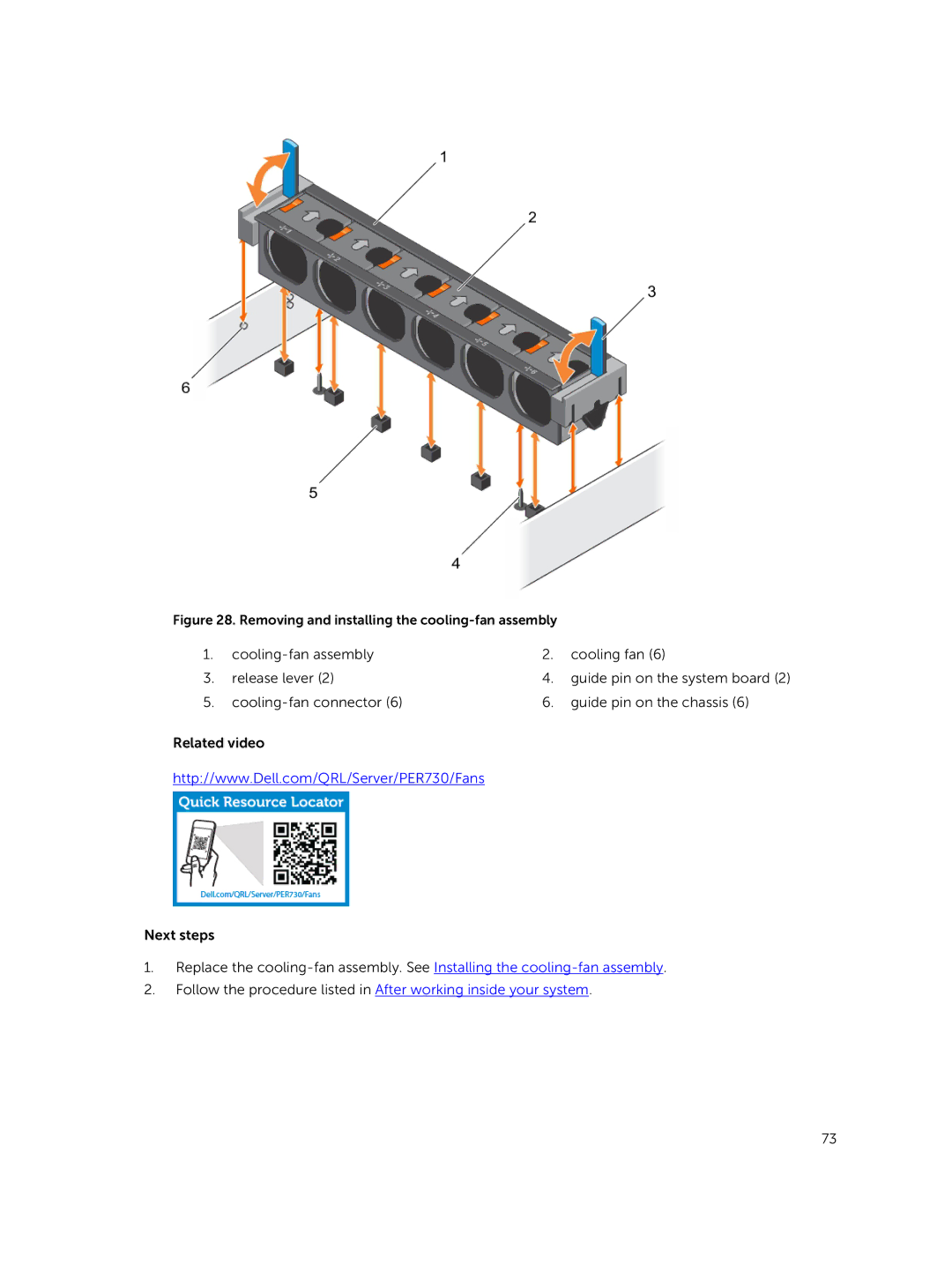
Figure 28. Removing and installing the |
| ||
1. |
| 2. | cooling fan (6) |
3. | release lever (2) | 4. | guide pin on the system board (2) |
5. | 6. | guide pin on the chassis (6) | |
Related video
http://www.Dell.com/QRL/Server/PER730/Fans
Next steps
1.Replace the
2.Follow the procedure listed in After working inside your system.
73