Installation Instructions | IM584000300 |
Spec. No. 584000300 (Model | Issue AB, April 3, 2013 |
|
|
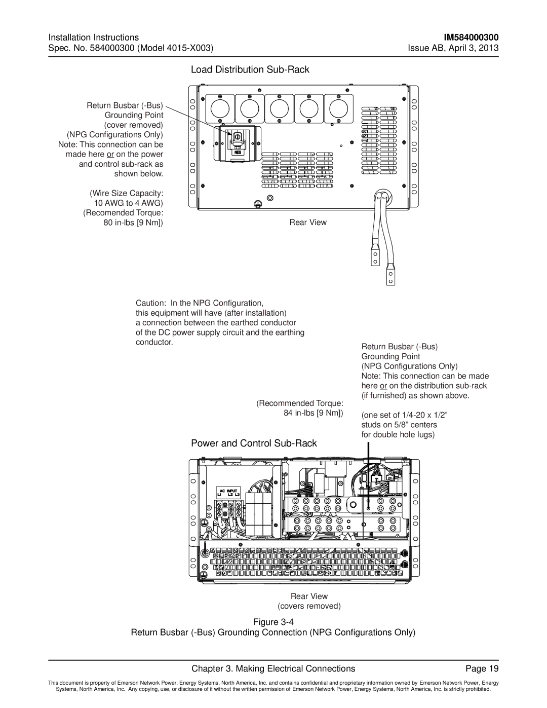
Load Distribution Sub-Rack
Return Busbar
(NPG Configurations Only) Note: This connection can be made here or on the power and control
(Wire Size Capacity: |
|
10 AWG to 4 AWG) |
|
(Recomended Torque: |
|
80 | Rear View |
Caution: In the NPG Configuration,
this equipment will have (after installation)
a connection between the earthed conductor of the DC power supply circuit and the earthing conductor.
(Recommended Torque:
84
Return Busbar
(NPG Configurations Only)
Note: This connection can be made here or on the distribution
(one set of
Power and Control |
Rear View
(covers removed)
Figure
Return Busbar
Chapter 3. Making Electrical Connections | Page 19 |
This document is property of Emerson Network Power, Energy Systems, North America, Inc. and contains confidential and proprietary information owned by Emerson Network Power, Energy
Systems, North America, Inc. Any copying, use, or disclosure of it without the written permission of Emerson Network Power, Energy Systems, North America, Inc. is strictly prohibited.