IM584000300 | Installation Instructions |
Issue AB, April 3, 2013 | Spec. No. 584000300 (Model |
|
|
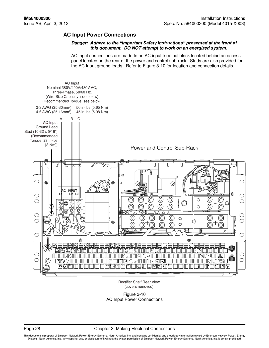
AC Input Power Connections
Danger: Adhere to the “Important Safety Instructions” presented at the front of this document. DO NOT attempt to work on an energized system.
AC input connections are made to an AC input terminal block located behind an access panel located on the rear of the power and control
AC Input
Nominal 380V/400V/480V AC,
(Wire Size Capacity: see below)
(Recommended Torque: see below)
50 |
| ||
45 |
| ||
A | B | C |
|
AC Input |
|
|
|
Ground Lead |
|
|
|
Stud |
|
|
|
(Recommended |
|
|
|
Torque: 23 |
|
|
|
[3 Nm]) |
| Power and Control |
|
|
|
| |
|
| - | - |
|
| + | + |
Rectifier Shelf Rear View
(covers removed)
Figure
AC Input Power Connections
Page 28 | Chapter 3. Making Electrical Connections |
This document is property of Emerson Network Power, Energy Systems, North America, Inc. and contains confidential and proprietary information owned by Emerson Network Power, Energy
Systems, North America, Inc. Any copying, use, or disclosure of it without the written permission of Emerson Network Power, Energy Systems, North America, Inc. is strictly prohibited.