IM584000300 | Installation Instructions |
Issue AB, April 3, 2013 | Spec. No. 584000300 (Model |
|
|
ACU+ CONTROLLER INITIALIZATION
Note: For factory configured systems, your controller was programmed with a configuration file that sets all adjustable parameters. Provided on a USB drive furnished with the system is an ACU+ configuration drawing
Refer to the ACU+ Controller Operation Instructions
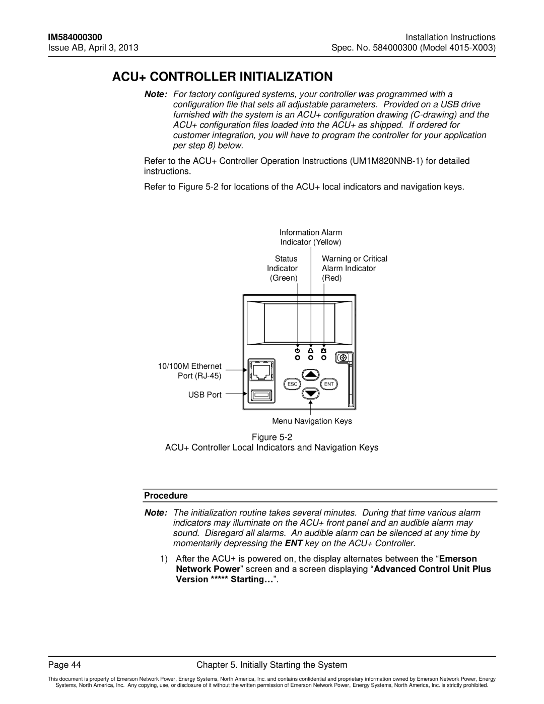
Refer to Figure
Information Alarm
Indicator (Yellow)
10/100M Ethernet Port
USB Port
Status | Warning or Critical |
Indicator | Alarm Indicator |
(Green) | (Red) |
ESC | ENT |
Menu Navigation Keys
Figure
ACU+ Controller Local Indicators and Navigation Keys
Procedure
Note: The initialization routine takes several minutes. During that time various alarm indicators may illuminate on the ACU+ front panel and an audible alarm may sound. Disregard all alarms. An audible alarm can be silenced at any time by momentarily depressing the ENT key on the ACU+ Controller.
1)After the ACU+ is powered on, the display alternates between the “Emerson Network Power” screen and a screen displaying “Advanced Control Unit Plus
Version ***** Starting…”.
Page 44 | Chapter 5. Initially Starting the System |
This document is property of Emerson Network Power, Energy Systems, North America, Inc. and contains confidential and proprietary information owned by Emerson Network Power, Energy
Systems, North America, Inc. Any copying, use, or disclosure of it without the written permission of Emerson Network Power, Energy Systems, North America, Inc. is strictly prohibited.
