IM584000300 | Installation Instructions |
Issue AB, April 3, 2013 | Spec. No. 584000300 (Model |
|
|
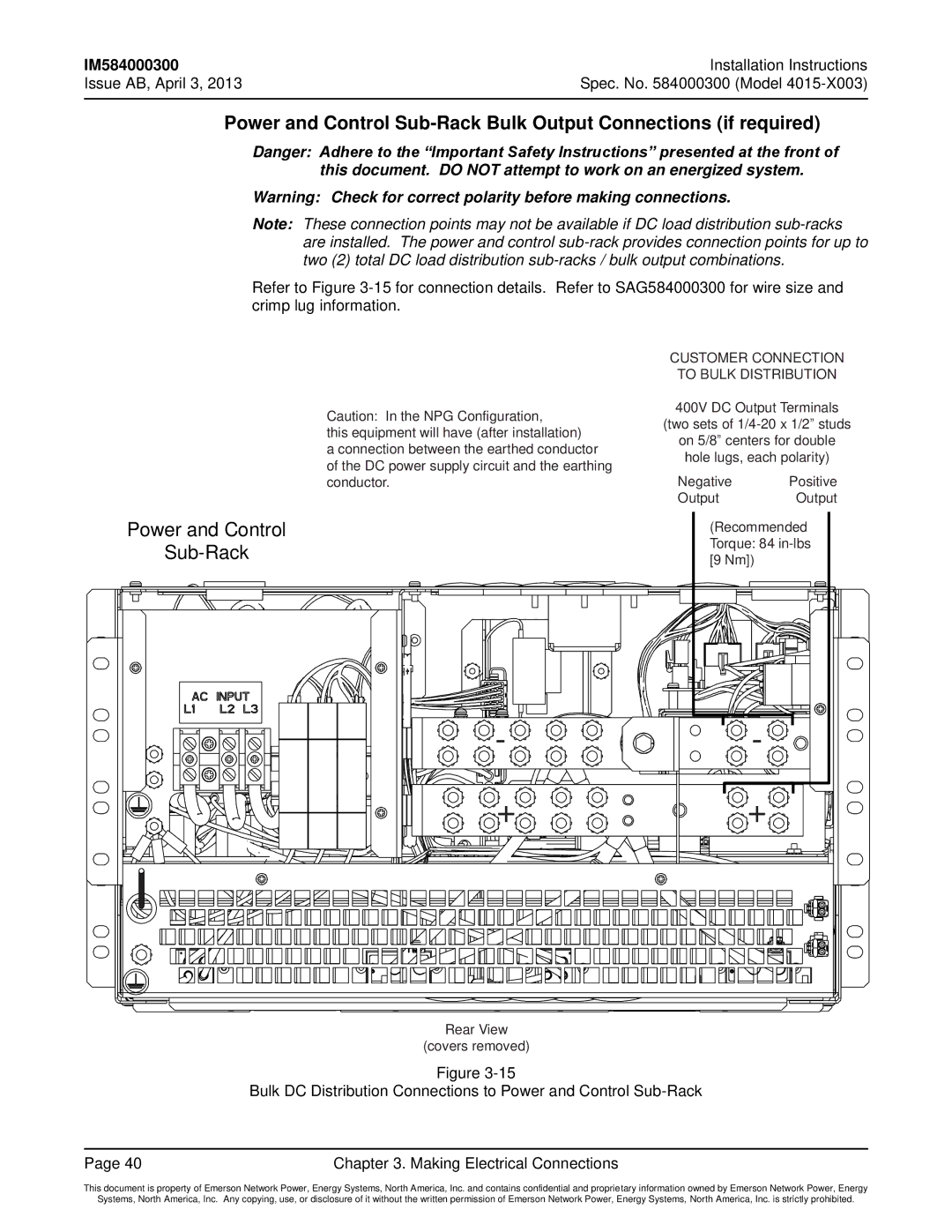
Power and Control
Danger: Adhere to the “Important Safety Instructions” presented at the front of this document. DO NOT attempt to work on an energized system.
Warning: Check for correct polarity before making connections.
Note: These connection points may not be available if DC load distribution
Refer to Figure
Caution: In the NPG Configuration,
this equipment will have (after installation)
a connection between the earthed conductor of the DC power supply circuit and the earthing conductor.
CUSTOMER CONNECTION TO BULK DISTRIBUTION
400V DC Output Terminals
(two sets of
on 5/8” centers for double hole lugs, each polarity)
Negative Positive
OutputOutput
Power and Control | (Recommended | |
| Torque: 84 | |
[9 Nm]) | ||
| ||
- | - | |
+ | + |
Rear View
(covers removed)
Figure
Bulk DC Distribution Connections to Power and Control
Page 40 | Chapter 3. Making Electrical Connections |
This document is property of Emerson Network Power, Energy Systems, North America, Inc. and contains confidential and proprietary information owned by Emerson Network Power, Energy
Systems, North America, Inc. Any copying, use, or disclosure of it without the written permission of Emerson Network Power, Energy Systems, North America, Inc. is strictly prohibited.