Installation Instructions | IM584000300 |
Spec. No. 584000300 (Model | Issue AB, April 3, 2013 |
|
|
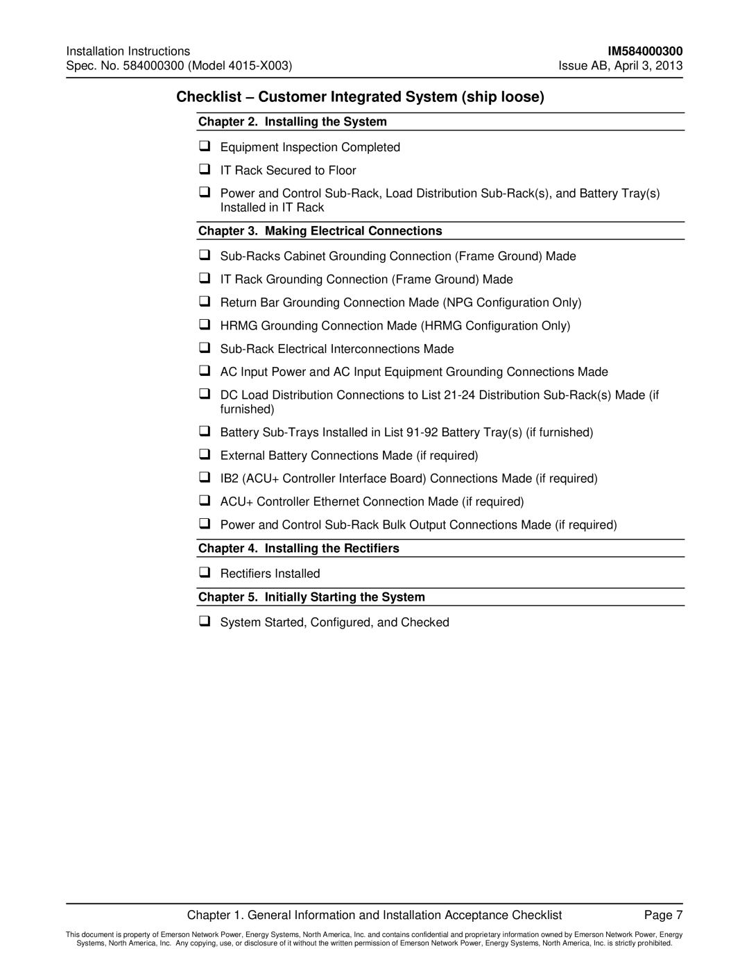
Checklist – Customer Integrated System (ship loose)
Chapter 2. Installing the System
Equipment Inspection Completed
IT Rack Secured to Floor
Power and Control
Chapter 3. Making Electrical Connections
IT Rack Grounding Connection (Frame Ground) Made
Return Bar Grounding Connection Made (NPG Configuration Only)
HRMG Grounding Connection Made (HRMG Configuration Only)
AC Input Power and AC Input Equipment Grounding Connections Made
DC Load Distribution Connections to List
Battery
External Battery Connections Made (if required)
IB2 (ACU+ Controller Interface Board) Connections Made (if required)
ACU+ Controller Ethernet Connection Made (if required)
Power and Control
Chapter 4. Installing the Rectifiers
Rectifiers Installed
Chapter 5. Initially Starting the System
System Started, Configured, and Checked
Chapter 1. General Information and Installation Acceptance Checklist | Page 7 |
This document is property of Emerson Network Power, Energy Systems, North America, Inc. and contains confidential and proprietary information owned by Emerson Network Power, Energy
Systems, North America, Inc. Any copying, use, or disclosure of it without the written permission of Emerson Network Power, Energy Systems, North America, Inc. is strictly prohibited.
