IM584000300 | Installation Instructions |
Issue AB, April 3, 2013 | Spec. No. 584000300 (Model |
|
|
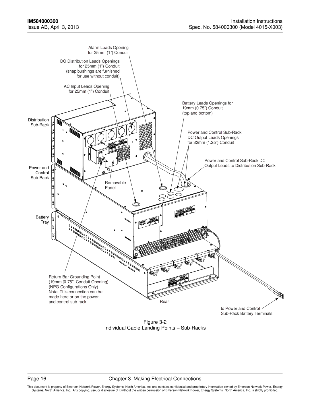
Alarm Leads Opening for 25mm (1”) Conduit
DC Distribution Leads Openings for 25mm (1”) Conduit (snap bushings are furnished for use without conduit)
AC Input Leads Opening for 25mm (1”) Conduit
Distribution
Power and
Control
Removable
Panel
Battery
Tray
Battery Leads Openings for 19mm (0.75”) Conduit (top and bottom)
Power and Control
Power and Control
Return Bar Grounding Point |
|
(19mm [0.75"] Conduit Opening) |
|
(NPG Configurations Only) |
|
Note: This connection can be |
|
made here or on the power |
|
and control | Rear |
| to Power and Control |
|
Figure
Individual Cable Landing Points –
Page 16 | Chapter 3. Making Electrical Connections |
This document is property of Emerson Network Power, Energy Systems, North America, Inc. and contains confidential and proprietary information owned by Emerson Network Power, Energy
Systems, North America, Inc. Any copying, use, or disclosure of it without the written permission of Emerson Network Power, Energy Systems, North America, Inc. is strictly prohibited.