Installing and Removing Modules
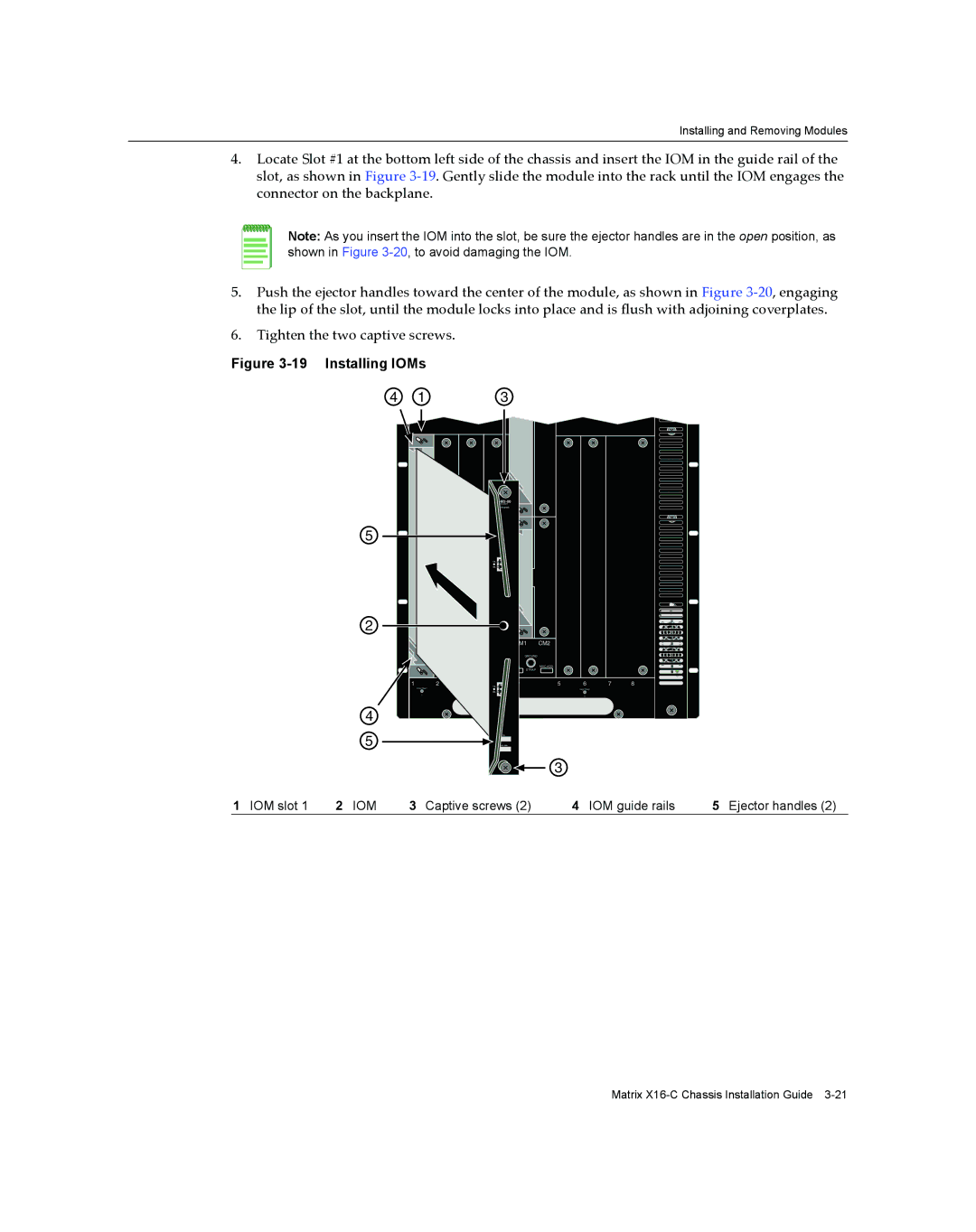
4.Locate Slot #1 at the bottom left side of the chassis and insert the IOM in the guide rail of the slot, as shown in Figure 3‐19. Gently slide the module into the rack until the IOM engages the connector on the backplane.
Note: As you insert the IOM into the slot, be sure the ejector handles are in the open position, as shown in Figure
5.Push the ejector handles toward the center of the module, as shown in Figure 3‐20, engaging the lip of the slot, until the module locks into place and is flush with adjoining coverplates.
6.Tighten the two captive screws.
Figure 3-19 Installing IOMs
4 | 1 | 3 |
5
2
4
5
|
|
|
|
|
|
| |
|
| 10G ENET |
|
|
|
|
|
|
| STATUS |
|
|
|
|
|
|
| TX TX |
|
|
|
|
|
|
| RX RX |
|
|
|
|
|
|
|
| CM1 | CM2 |
|
|
|
|
|
| GROUND |
|
|
|
|
|
|
| S/N: | MAC ADD. |
|
|
|
|
|
| STRAP |
|
|
|
|
1 | 2 | TX TX | 1 | 5 | 6 | 7 | 8 |
FAN TRAY |
| FAN TRAY |
|
| FAN TRAY |
|
|
|
| RX RX |
|
|
|
|
|
1 |
| 2 |
|
| 3 |
|
|
S/N:
MAC ADD.
3
1 IOM slot 1 | 2 IOM | 3 Captive screws (2) | 4 IOM guide rails | 5 Ejector handles (2) |
Matrix