LEDs and Reset Button
LEDs and Reset Button
The following sections describe LED indications for the following:
•Power supplies and fan trays
•IOM, CM, and FMs (with CM Reset button)
Power Supply LEDs
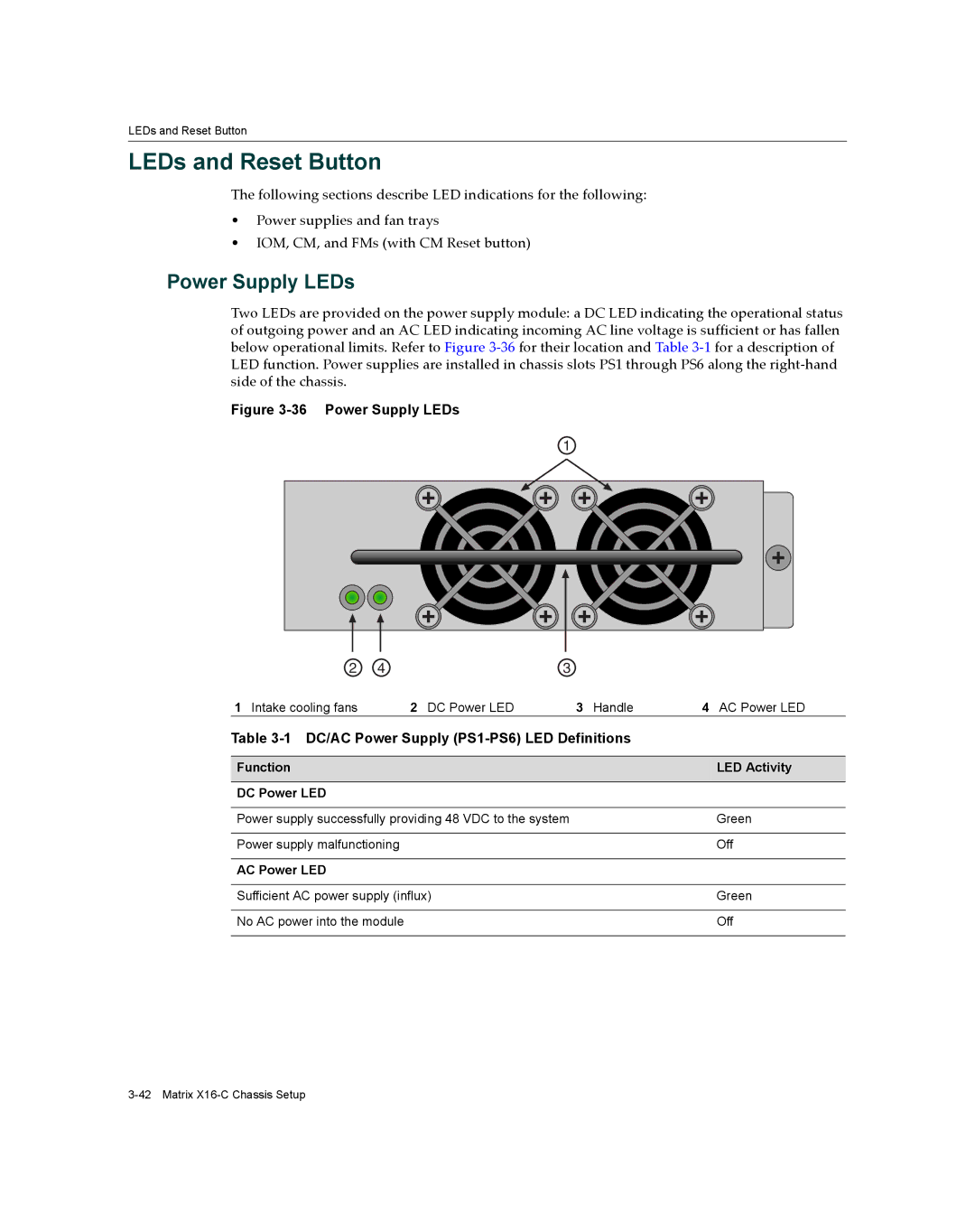
Two LEDs are provided on the power supply module: a DC LED indicating the operational status of outgoing power and an AC LED indicating incoming AC line voltage is sufficient or has fallen below operational limits. Refer to Figure 3‐36 for their location and Table 3‐1 for a description of LED function. Power supplies are installed in chassis slots PS1 through PS6 along the right‐hand side of the chassis.
Figure 3-36 Power Supply LEDs
1
2 | 4 | 3 |
|
1 Intake cooling fans | 2 DC Power LED | 3 Handle | 4 AC Power LED |
Table |
| ||
|
|
|
|
Function |
|
| LED Activity |
|
|
|
|
DC Power LED |
|
|
|
|
| ||
Power supply successfully providing 48 VDC to the system | Green | ||
|
|
| |
Power supply malfunctioning |
| Off | |
|
|
|
|
AC Power LED |
|
|
|
|
|
| |
Sufficient AC power supply (influx) |
| Green | |
|
|
| |
No AC power into the module |
| Off | |
|
|
|
|