Optional Cable Management Kit
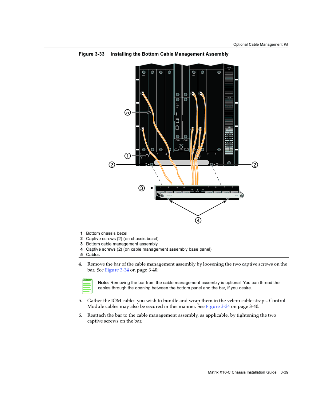
Figure 3-33 Installing the Bottom Cable Management Assembly
1 | 2 | 3 | 4 |
1 |
|
| 2 |
5 | 6 | 7 | 8 |
| 3 |
|
|
X16
1Bottom chassis bezel
2Captive screws (2) (on chassis bezel)
3Bottom cable management assembly
4Captive screws (2) (on cable management assembly base panel)
5Cables
4.Remove the bar of the cable management assembly by loosening the two captive screws on the bar. See Figure 3‐34 on page 3‐40.
Note: Removing the bar from the cable management assembly is optional. You can thread the cables through the opening between the bottom panel and the bar, if you desire.
5.Gather the IOM cables you wish to bundle and wrap them in the velcro cable straps. Control Module cables may also be secured in this manner. See Figure 3‐34 on page 3‐40.
6.Reattach the bar to the cable management assembly, as applicable, by tightening the two captive screws on the bar.
Matrix