Installing and Removing a Power Supply
8.Position the power supply with the flange and captive screw pointing up and align with the slot opening.
Caution: Forcing a misaligned power supply into place can damage the power supply or chassis backplane.
Precaución: Colocar de manera forzada una fuente de poder o no colocarla bien alineada podría dañarla y/o maltratar el panel posterior del chasis.
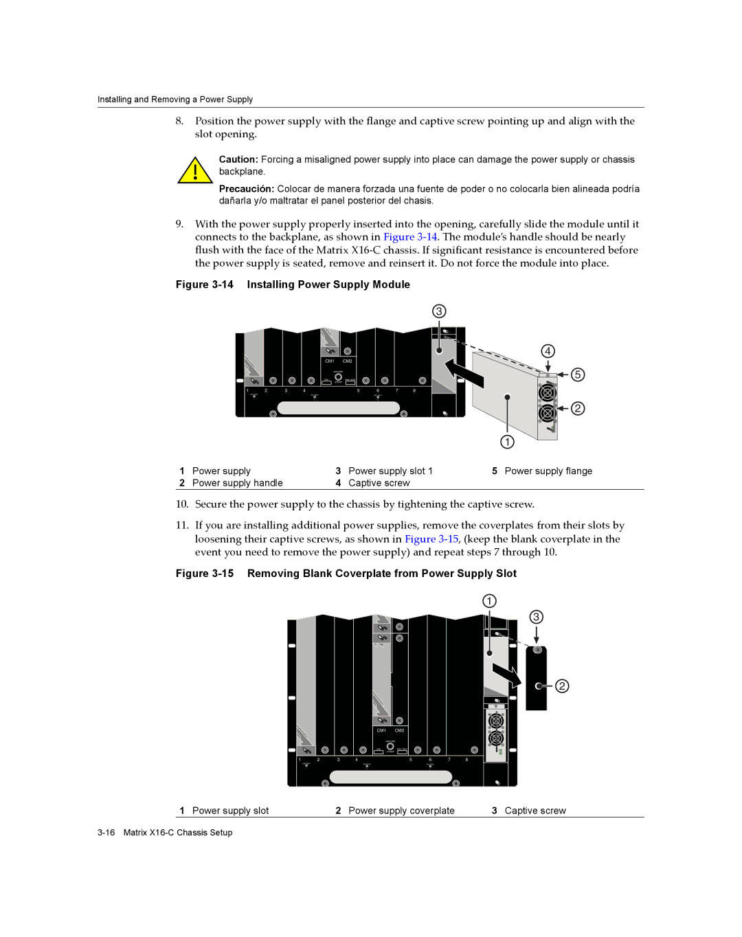
9.With the power supply properly inserted into the opening, carefully slide the module until it connects to the backplane, as shown in Figure 3‐14. The module’s handle should be nearly flush with the face of the Matrix X16‐C chassis. If significant resistance is encountered before the power supply is seated, remove and reinsert it. Do not force the module into place.
Figure 3-14 Installing Power Supply Module
|
|
| CM1 | CM2 |
|
|
|
|
|
| GROUND |
|
|
| |
|
|
| S/N: | MAC ADD. |
|
|
|
|
|
|
| STRAP |
|
|
|
1 | 2 | 3 | 4 | 5 | 6 | 7 | 8 |
| FAN TRAY |
| FAN TRAY |
| FAN TRAY |
|
|
| 1 |
| 2 |
| 3 |
|
|
3 |
4 |
5
2
|
|
|
| 1 |
|
|
|
|
|
|
|
| |
1 | Power supply | 3 | Power supply slot 1 | 5 Power supply flange | ||
2 | Power supply handle | 4 | Captive screw |
|
|
|
10.Secure the power supply to the chassis by tightening the captive screw.
11.If you are installing additional power supplies, remove the coverplates from their slots by loosening their captive screws, as shown in Figure 3‐15, (keep the blank coverplate in the event you need to remove the power supply) and repeat steps 7 through 10.
Figure 3-15 Removing Blank Coverplate from Power Supply Slot
CM1 | CM2 |
GROUND | |
S/N: | MAC ADD. |
| STRAP |
1 | 2 | 3 | 4 | 5 | 6 | 7 | 8 |
| FAN TRAY |
| FAN TRAY |
| FAN TRAY |
|
|
| 1 |
| 2 |
| 3 |
|
|
1
3
2
1 Power supply slot | 2 Power supply coverplate | 3 Captive screw |