Setting Up the Matrix
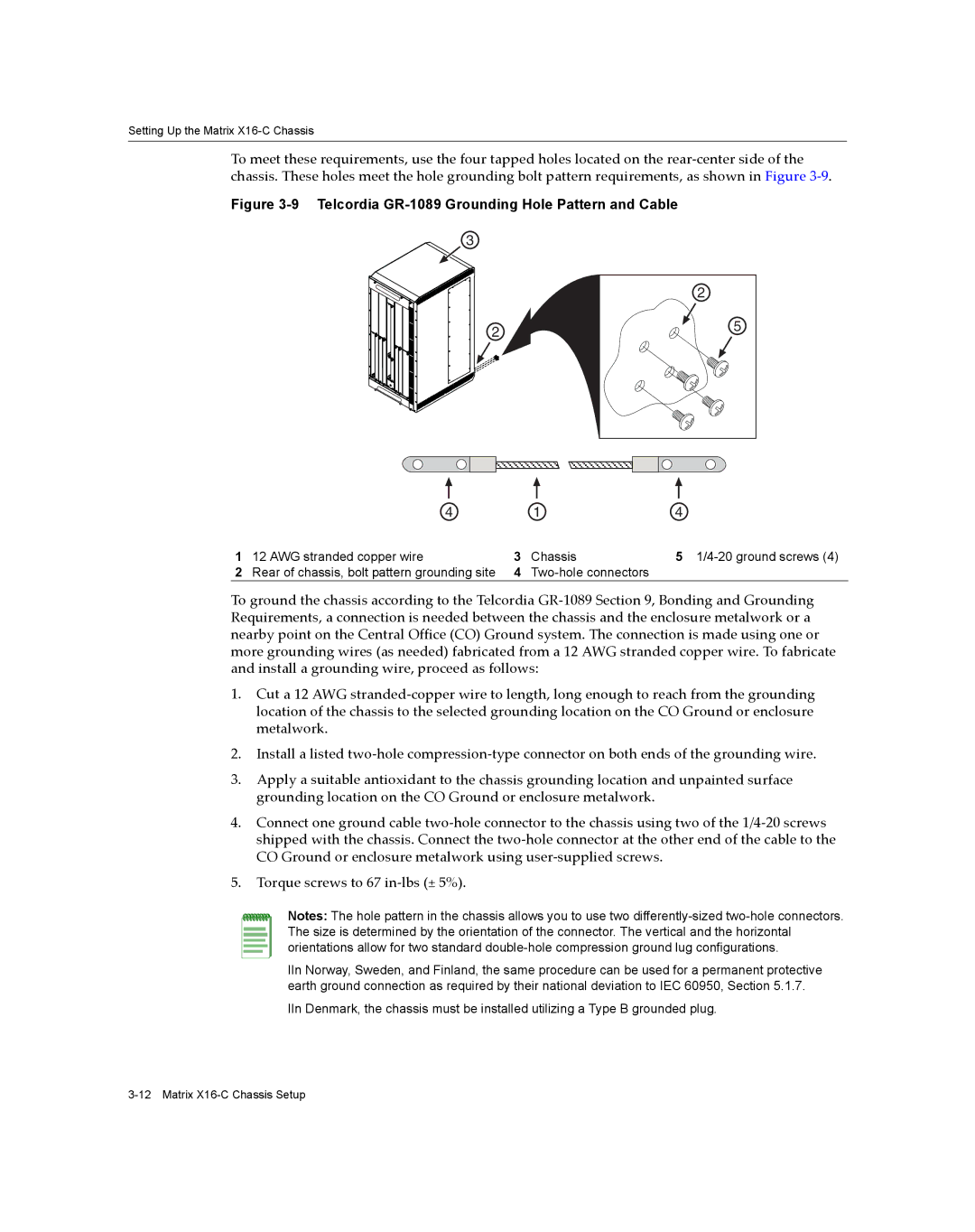
To meet these requirements, use the four tapped holes located on the rear‐center side of the chassis. These holes meet the hole grounding bolt pattern requirements, as shown in Figure 3‐9.
Figure 3-9 Telcordia GR-1089 Grounding Hole Pattern and Cable
3
2
2
5
| 4 |
| 1 | 4 |
1 | 12 AWG stranded copper wire | 3 | Chassis | 5 |
2 | Rear of chassis, bolt pattern grounding site | 4 |
|
To ground the chassis according to the Telcordia GR‐1089 Section 9, Bonding and Grounding Requirements, a connection is needed between the chassis and the enclosure metalwork or a nearby point on the Central Office (CO) Ground system. The connection is made using one or more grounding wires (as needed) fabricated from a 12 AWG stranded copper wire. To fabricate and install a grounding wire, proceed as follows:
1.Cut a 12 AWG stranded‐copper wire to length, long enough to reach from the grounding location of the chassis to the selected grounding location on the CO Ground or enclosure metalwork.
2.Install a listed two‐hole compression‐type connector on both ends of the grounding wire.
3.Apply a suitable antioxidant to the chassis grounding location and unpainted surface grounding location on the CO Ground or enclosure metalwork.
4.Connect one ground cable two‐hole connector to the chassis using two of the 1/4‐20 screws shipped with the chassis. Connect the two‐hole connector at the other end of the cable to the CO Ground or enclosure metalwork using user‐supplied screws.
5.Torque screws to 67 in‐lbs (± 5%).
Notes: The hole pattern in the chassis allows you to use two
IIn Norway, Sweden, and Finland, the same procedure can be used for a permanent protective earth ground connection as required by their national deviation to IEC 60950, Section 5.1.7.
IIn Denmark, the chassis must be installed utilizing a Type B grounded plug.