LEDs and Reset Button
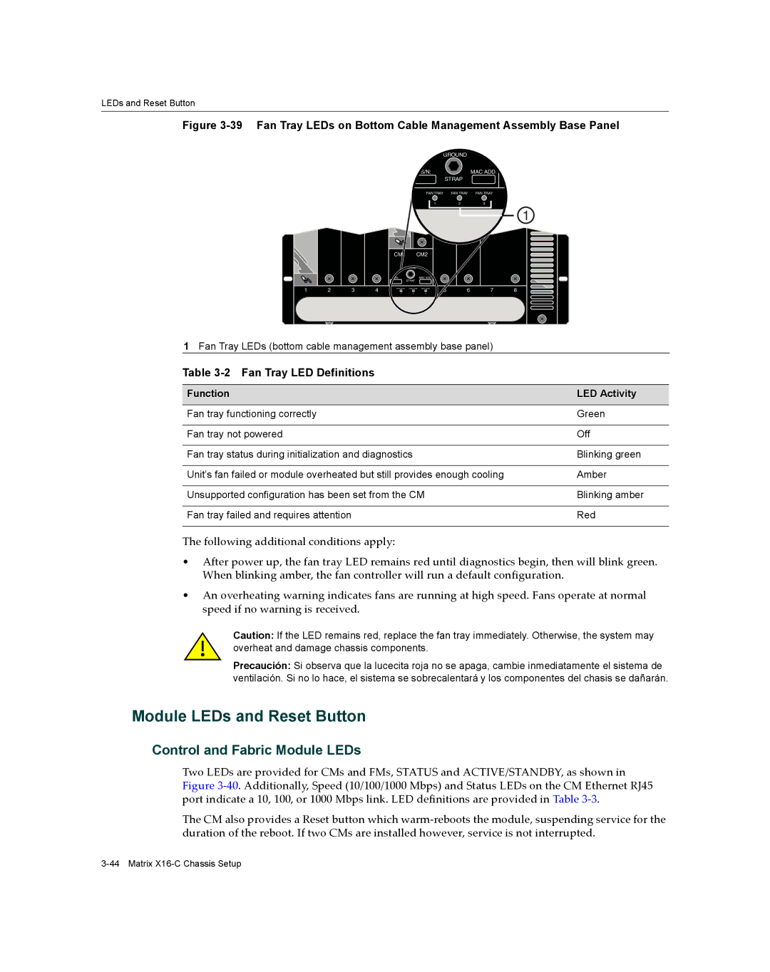
Figure 3-39 Fan Tray LEDs on Bottom Cable Management Assembly Base Panel
GROUND |
| |
S/N: |
| MAC ADD. |
| STRAP |
|
FAN TRAY | FAN TRAY | FAN TRAY |
1 | 2 | 3 |
1
|
|
|
| CM1 | CM2 |
|
|
|
| ||
|
|
|
| GROUND |
|
|
|
|
| ||
|
|
|
| S/N: | STRAP | MAC ADD. |
|
|
|
| |
|
|
|
|
|
|
|
|
|
| ||
1 | 2 | 3 | 4 | FAN TRAY | FAN TRAY | FAN TRAY | 5 | 6 | 7 | 8 | |
1 | 2 | 3 | |||||||||
|
|
|
|
|
|
|
| ||||
1Fan Tray LEDs (bottom cable management assembly base panel)
Table 3-2 Fan Tray LED Definitions
Function | LED Activity |
|
|
Fan tray functioning correctly | Green |
|
|
Fan tray not powered | Off |
|
|
Fan tray status during initialization and diagnostics | Blinking green |
|
|
Unit’s fan failed or module overheated but still provides enough cooling | Amber |
|
|
Unsupported configuration has been set from the CM | Blinking amber |
|
|
Fan tray failed and requires attention | Red |
|
|
The following additional conditions apply:
•After power up, the fan tray LED remains red until diagnostics begin, then will blink green. When blinking amber, the fan controller will run a default configuration.
•An overheating warning indicates fans are running at high speed. Fans operate at normal speed if no warning is received.
Caution: If the LED remains red, replace the fan tray immediately. Otherwise, the system may overheat and damage chassis components.
Precaución: Si observa que la lucecita roja no se apaga, cambie inmediatamente el sistema de ventilación. Si no lo hace, el sistema se sobrecalentará y los componentes del chasis se dañarán.
Module LEDs and Reset Button
Control and Fabric Module LEDs
Two LEDs are provided for CMs and FMs, STATUS and ACTIVE/STANDBY, as shown in Figure 3‐40. Additionally, Speed (10/100/1000 Mbps) and Status LEDs on the CM Ethernet RJ45 port indicate a 10, 100, or 1000 Mbps link. LED definitions are provided in Table 3‐3.
The CM also provides a Reset button which warm‐reboots the module, suspending service for the duration of the reboot. If two CMs are installed however, service is not interrupted.