LEDs and Reset Button
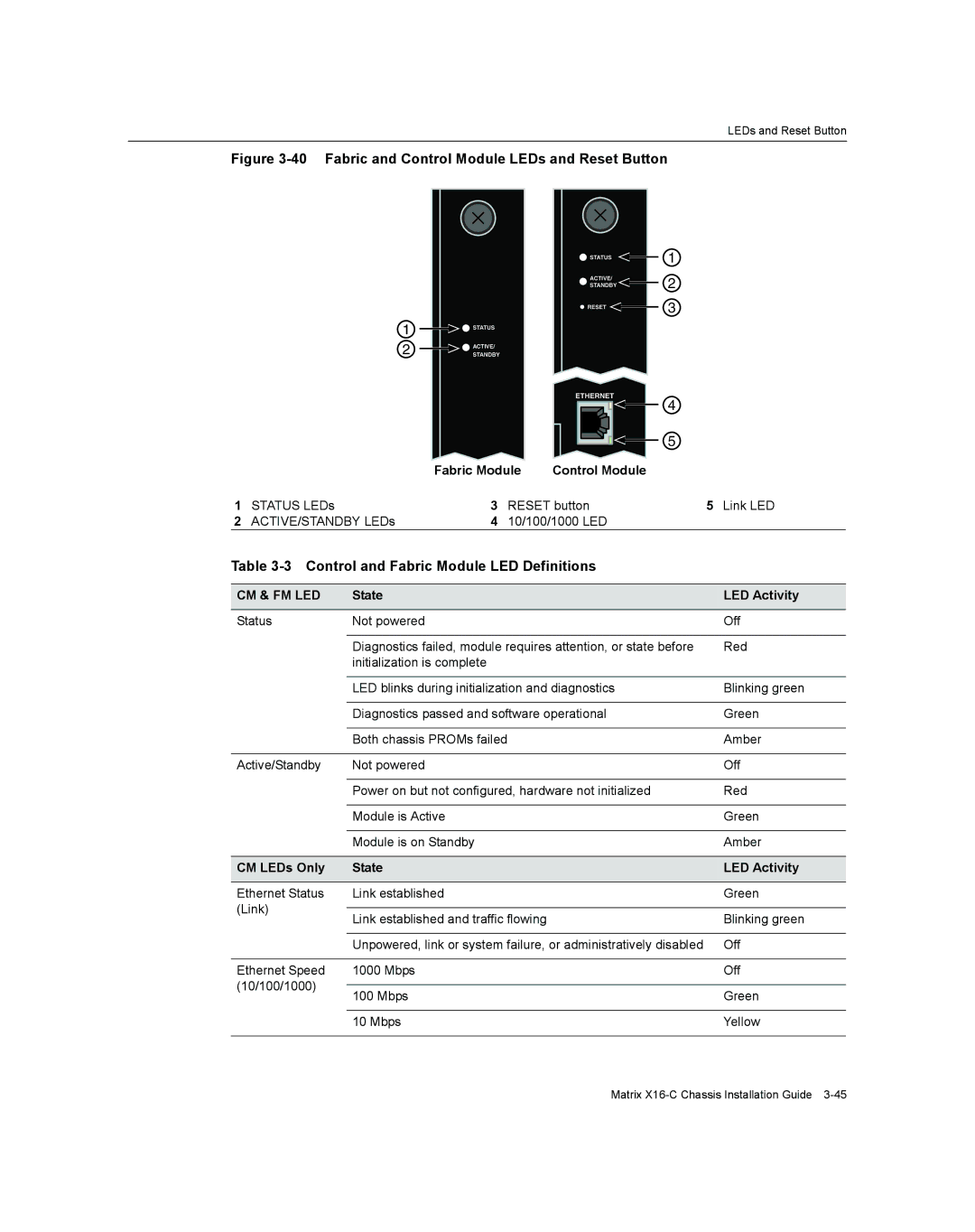
Figure 3-40 Fabric and Control Module LEDs and Reset Button
![]() STATUS
STATUS
ACTIVE/
STANDBY
![]() RESET
RESET ![]()
1
2
3
1
2
![]()
![]() STATUS
STATUS
![]() ACTIVE/
ACTIVE/
STANDBY
ETHERNET |
4
5
|
| Fabric Module | Control Module |
| |
1 | STATUS LEDs | 3 | RESET button | 5 Link LED | |
2 | ACTIVE/STANDBY LEDs | 4 | 10/100/1000 LED |
| |
Table 3-3 Control and Fabric Module LED Definitions
CM & FM LED | State | LED Activity | |
|
|
| |
Status | Not powered | Off | |
|
|
| |
| Diagnostics failed, module requires attention, or state before | Red | |
| initialization is complete |
| |
|
|
| |
| LED blinks during initialization and diagnostics | Blinking green | |
|
|
| |
| Diagnostics passed and software operational | Green | |
|
|
| |
| Both chassis PROMs failed | Amber | |
|
|
| |
Active/Standby | Not powered | Off | |
|
|
| |
| Power on but not configured, hardware not initialized | Red | |
|
|
| |
| Module is Active | Green | |
|
|
| |
| Module is on Standby | Amber | |
|
|
| |
CM LEDs Only | State | LED Activity | |
|
|
| |
Ethernet Status | Link established | Green | |
(Link) |
|
| |
Link established and traffic flowing | Blinking green | ||
| |||
|
|
| |
| Unpowered, link or system failure, or administratively disabled | Off | |
|
|
| |
Ethernet Speed | 1000 Mbps | Off | |
(10/100/1000) |
|
| |
100 Mbps | Green | ||
| |||
|
|
| |
| 10 Mbps | Yellow | |
|
|
|
Matrix