TM-T88IIIseries
Matsumoto Minami Plant
Revisions Design Section Sheet Rev. No Document
Revision Sheet
TM-T88 III series
Sheet Rev
Confidential
Rev Sheet
TM-T88IIIseries
REV Sheet Changed Contents
General Features
III
Confidentiality Agreement
Trademarks
General Features
Table of Contents
Options and Consumables
Case Specifications
Commands
FS q n xL xH yL yH d1
Appendix F Notes on Using the Drawer KICK-OUT Connector
Appendix K Comparison Table Between TM-T88 III and TM-T88
General Specifications
Printing Specifications
Character Specifications
Character Size
2 Supporting Character on Each Model Type
Paper Roll Supply Device
Paper Specification
Autocutter
Printable Area
1 Paper Roll Printable Area
Printing and Cutting Positions
Internal Buffer
EMI
Electrical Characteristics
EMI and Safety Standards Applied
Reliability
Environmental Conditions
Installation
Switching between online and offline
Configuration
Specifications
Interface 1 RS-232 serial interface
1 TM-T88IIIPrinter Status and Signals
GS a
2 XON/XOFF Transmit Timing
DLE ENQ 1 or DLE ENQ 2 commands
1.4 XON/XOFF transmit timing
Reset Switching
Serial interface connection example
4 Reset DC Characteristics
1 Minimum Reset Pulse Width pin
Ieee 1284 Bidirectional Parallel Interface
Compatibility Mode
Reverse Mode Data Transmission from Printer to Host
Dkstatus
Interface Pin Assignments for Each Mode
GND
Logic-H Signal Sender Characteristics
+5 V Signal Sender Characteristics
Data Receiving Timing Compatibility Mode
Data
TRS
Near end detection
CS1 CS2
Specifications RS-485 compatible
3 RS-485 Serial Interface
DR1 DR2
Confidential
RD2
SD1
SD2 RD1
DR1
CS1
Other Interfaces
1 Power Supply Connector Pin Assignments
Connectors Interface Connectors
Power Supply Connector
Shell
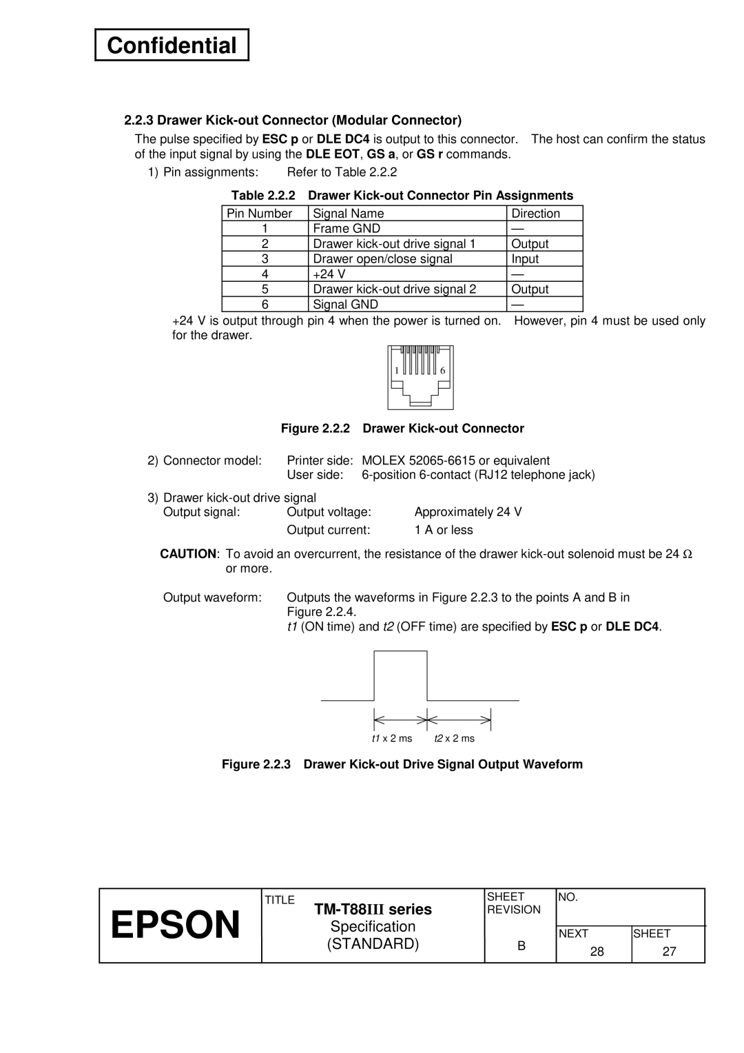
Drawer Kick-out Connector Modular Connector
2 Drawer Kick-out Connector Pin Assignments
4 Drawer Circuitry
ESC ∗
List of commands
Functions
ESC d
ESC a
ESC c
ESC p
GS r
GS h
GS k
GS v
DC4 Can
1 Katakana
2 PC850 Multilingual
3 PC860 Portuguese
4 PC863 Canadian-French
5 PC865 Nordic
16 WPC1252
17 PC866 Cyrillic#2
18 PC852 Latin2
19 PC858
20 Thai character code
21 Thai character code
22 Thai character code
23 Thai character code
24 Thai character code
25 Thai character code
26 Thai character code
255 Space
International Character Set
Switches and Buttons Power Button
Panel Buttons
2 Transmission Speed
DIP Switches
XON/XOFF DTR/DSR
DIP Switch
4 DIP Switch 2-3
7 DIP Switch 2-3
Parallel interface specification DIP Switch
6 DIP Switch
Panel LED Indicators
1 Standby State Indication
Self-test
Hexadecimal Dumping
C D E F G H I J
2 Errors That Can Possibly Recover
Error Processing Error Types
1 Errors That Automatically Recover
CPU
Printer Operation When an Error Occurs
Unrecoverable Errors
Cover Open Sensor
Paper Sensors
Cover Open Button
Print Buffer-full Printing
Mode General Description
Setting Values in Standard and Page Modes
Formatting of Print Data in the Printable Area
ESC T n
12.2 Character Data Developing Position
12.3 Print Data Developing Position
Color
Case Specifications
External Dimensions and Mass
External Appearance
Options
Standard Accessories
Options and Consumables
Consumables
Explanation of Terms
Commands
Command Notation
When font B Dots is selected, this
Control Commands
Ascii
ESC FF, ESC L, ESC S
Ascii Can
DLE EOT n
Ascii DLE EOT
Confidential
Confidential
DLE ENQ n
Ascii DLE ENQ
DLE DC4 n m t
Ascii DLE DC4
ESC SP n
Ascii ESC
ESC ! n
ESC −
ESC $ nL nH
ESC % n
ESC &, ESC ?
ESC & y c1 c2 x1 d1 Dy ⋅ Xk d1 Dy ⋅ xk
ESC %, ESC ?
When font B 9 ⋅ 17 is selected dots
ESC ∗
NL nH d1...dk
MSB
When 24-dot bit image is selected
ESC n
ESC
ESC 3 n
ESC 2 , GS P
ESC
ESC = n
ESC ? n
ESC & , ESC %
ESC @
ESC D n1...nk NUL
ESC E n
ESC G n
ESC J n
ESC L
ESC M n
ESC R n
ESC S
ESC T n
ESC $ , ESC L , ESC W , ESC \ , GS $ , GS P , GS \
ESC V n
ESC !, ESC −
ESC W xL xH yL yH dxL dxH dyL dyH
ASC ESC
Paper
ESC \ nL nH
ESC a n
ABC Abcd Abcde
ESC c 3 n
ESC c 4 n
ESC 2 , ESC
ESC c 5 n
ESC d n
ESC p m t1 t2
Character Code Tables , Appendix H
Name Turns on/off upside-down printing mode Format
FS g 1 m a1 a2 a3 a4 nL nH d1...dk
FS g 2 m a1 a2 a3 a4 nL nH
NUL
Bytes or more space is required in the receive buffer
FS p n m
FS q n xL xH yL yH d1...dk1...xL xH yL yH d1...dkn
114 113
Dots = 768 dots 256 ⋅
GS ! n
117 116
GS $ nL nH
GS ∗ x y d1...dx ⋅
GS a pL pH n m
GS / m
Name Start/end macro definition Format
GS f , GS k
GS B n
GS H n
TM-T88
GS I n
Epson
Kanji Japanese
125 124
GS L nL nH
GS P x y
② Ascii
① GS V m ② GS V m n
① Ascii
GS W nL nH
130 129
GS \ nL nH
GS r t m
GS a n
134 133
135 134
GS f n
ESC ! , GS
① GS k m d1...dk NUL ② GS k m n d1...dn
UPC-A
139 138
140 139
Code B
Shift
Code a
Code C
Transmits drawer kick-out connector status
GS r n
143 142
GS v 0 m xL xH yL yH d1....dk
GS w n
CODE39, ITF, Codabar
Bit Off/On Hex Decimal Function
Kanji Control Commands
FS ! n
FS − , FS W , GS
Name Select Kanji character mode Format
FS − n
FS & , FS C
150 149
FS C n
Kanji System
FS S n1 n2
N2 ≤
FS W n
FS ! , GS
Appendix a Miscellaneous Notes
Table A.1 Paper Feeding Amount
Other Notes
App.4 App.3
Appendix B Paper Roll Setup
Replacing the Paper Roll
Table C.1 Adjustment Positions
Figure C.1 Near-end Adjusting Position
Figure C.2 Changing the Near-end Adjusting Position
Appendix D Recovery from the Auto Cutter Error
Appendix E Print Head Cleaning
Figure E.1 Print Head Thermal Elements
Appendix F Notes on Using the Drawer KICK-OUT Connector
Appendix G Transmission Status Identification
Table G.1 Transmission Status Identification
FCA480H FCBC80H
Appendix H Configuring the Space
Table H.1 Space Page Top Address
Figure H.2 9 ⋅ 17 Font
Appendix I Example Printing in page Mode
Figure I.1 Page Mode Example
Figure I.2 Page Mode Example
Print #1,ABCDEFGHIJKLMNOPQRST1234567890
Figure I.3 Page Mode Example
Appendix J CODE128 BAR Code
Description of the CODE128 Bar Code
Code Tables
7B,41 123,66
7B,41 123,65
Appendix K Comparison Table Between TM-T88IIIAND TM-T88II