Nios Embedded Processor
Nios Embedded Processor Programmer’s Reference Manual
Revision History
Revision Date Description
How to Contact Altera
Information Type Access USA & Canada All Other Locations
Visual Cue Meaning
Typographic Conventions
Conventions
Courier type
Altera Corporation
Contents
Bit Instruction Set
Viii
Contents
Index 107
Altera Corporation
List of Tables
Xii
Audience
Nios CPU Architecture
Nios CPU Details Bit Nios CPU
General-Purpose Registers
Register Groups
Programmer’s Model
Clrie
K Register
Program Counter
Control Registers
Interrrupt Enable IE
Condition Code Flags
Condition Code Flags
Memory Access Overview
Address Contents
Typical 32-bit Nios CPU Program/Data Memory at Address
Code Example 1 Reading a Single Byte from Memory
Writing to Memory or Peripherals
Addressing Modes
Bit Immediate Value
Instructions Using 5/16-bit Immediate Values
Code Example 3 The Addi Instruction Used with/without a PFX
Partial Width Register-Indirect
Instructions Using Full Width Register-indirect Addressing
Full Width Register-Indirect
Instruction Address Register Data Register
Instruction Address Register
Full Width Register-Indirect with Offset
Partial Width Register-Indirect with Offset
Offset Range without PFX
Relative-Branch Instructions
Instruction Address
Byte/Half-word Index Range
Absolute-Jump Instructions
Trap Instructions
Conditional Instructions
Exception Handling Overview
Exception Vector Table
External Hardware Interrupt Sources
Internal Exception Sources
Register Window Overflow
Direct Software Exceptions Trap Instructions
Exception Processing Sequence
Register Window Usage
Return-Address
Simple and Complex Exception Handlers
Pipeline Implementation
Branch Delay Slots
BR Branch Delay Slot Example
Pipeline Operation
Direct CWP Manipulation
Notation Details
Notation Meaning
Instruction Format Sheet 1
Instruction Format Sheet 2
Bit Major Opcode Table Sheet 1
Opcode Mnemonic Format Summary
Bit Major Opcode Table Sheet 2
USR0
Bit Major Opcode Table Sheet 3
MUL
GNU Compiler/Assembler Pseudo-instructions
Psuedo-Instruction
Operator Description Operation
Altera Corporation
Bit Instruction Set
ABS %rA
ABS
Absolute Value
ABS %r6
ADD %rA,%rB
ADD
Add Without Carry
ADD %L3,%g0 ADD %g0 to %L3
Addi
Add Immediate
PFX %hiconst
Bitwise Logical
%rA,%rB
PFX %hi16383
PFX %hiconst Andn %rA,%loconst
Andn
Bitwise Logical and not
PFX %hi16384
ASR
Arithmetic Shift Right
Asri
Arithmetic Shift Right Immediate
Bit Generate
Bgen %rA,IMM5
Branch
BR MainLoop
BSR
Branch To Subroutine
BSR SendCharacter
Call
Call Subroutine
Compare
CMP %rA,%rB
Cmpi & %rA,IMM5
Cmpi
Compare Immediate
Cmpi %i3,24 compare %i3 to
EXT16d %rA,%rB
EXT16d
Half-Word Extract Dynamic
LD %i3,%i4 get 32 bits from %i4 & 0xFF.FF.FF.FC
EXT16s %rA,IMM1
EXT16s
Half-Word Extract Static
EXT16s %L3,1 %L3 gets upper short int of itself
EXT8d %rA,%rB
EXT8d
Byte-Extract Dynamic
LD %g4,%i0 get 32 bits from %i0 & 0xFF.FF.FF.FC
EXT8s %rA,IMM2
EXT8s
Byte-Extract Static
EXT8s %g6,3 %g6 gets the 3rd byte of itself
FILL16 %r0,%rA
FILL16
Half-Word Fill
FILL16 %r0,%i3 %r0 gets 2 copies of %i30..15
FILL8 %r0,%rA
FILL8
Byte-Fill
FILL8 %r0,%o3 %r0 gets 4 copies of %o30..7
IF0
Equivalent to SKP1 Instruction
IF0 %rA,IMM5
IF1
Equivalent to SKP0 Instruction
IFRnz
Equivalent to SKPRz Instruction
IFRnz %rA IFRnz %o3
IFRz
Equivalent to SKPRnz Instruction
IFS
Conditionally Execute Next Instruction
JMP %rA
JMP
Computed Jump
JMP %o7 return
Load 32-bit Data From Memory
Word offset
Load 32-bit Data From Memory Pointer Addressing Mode
LDP
LDP %o3,%L2,3 Load %o3 from %L2 +
LDS
Lret
Equivalent to JMP %o7
Lret return
LSL %rA,%rB
LSL
Logical Shift Left
LSL %L3,%g0 Shift %L3 left by %g0 bits
Lsli
Logical Shift Left Immediate
LSR
Logical Shift Right
Lsri
Logical Shift Right Immediate
MOV %rA,%rB
MOV
Register-to-Register Move
MOV %o0,%L3 copy %L3 into %o0
Movhi
Move Immediate Into High Half-Word
Movhi %rA,IMM5
Movi
Move Immediate
Movi %rA,IMM5
Mstep %rA
Mstep
Multiply-Step
Mstep %r1
Multiply
MUL %rA
MUL %i5
NEG %rA
NEG
Arithmetic Negation
NEG %o4
NOP
Equivalent to MOV %g0, %g0
NOP do nothing
Not %rA
Not
Logical Not
Not %o4
PFX %hiconst Or %ra,%loconst
Bitwise Logical or
Or %rA,%rB
Or %i0,%i1 or %i1 into %i0
PFX
Prefix
PFX 3 affects next instruction
Rdctl
Read Control Register
Rdctl %rA
Restore
Restore Caller’s Register Window
Restore restores caller’s register window
RET
Equivalent to JMP %i7
RLC
Rotate Left Through Carry
RRC
Rotate Right Through Carry
Save
Save Caller’s Register Window
Save %sp,-IMM8
SEXT16
Sign Extend 16-bit Value
SEXT16 %rA
SEXT8
Sign Extend 8-bit Value
SEXT8 %rA
SKP0
Skip If Register Bit Is
SKP1
SKP1 %rA,IMM5
SKPRnz
Skip If Register Not Equal To
SKPRz
Skip If Register Equals
SKPRz %rA SKPRz %o3
Skps
Skip On Condition Code
Skps ccIMM4 Skps ccne
Store 32-bit Data To Memory
ST16d
ST16s %rA,%r0,IMM1
ST16s
Store 16-Bit Data To Memory Static Half-Word-Offset Address
PFX Y ST16s %rA,%r0,Y 1
ST8d %rA,%r0
ST8d
Store 8-Bit Data To Memory Computed Byte-Pointer Address
FILL8 %r0,%g3
Movi %g4,12
ST8s
Store 8-bit Data To Memory Static Byte-Offset Address
Mem%g4 + 36 +
Store 32-bit Data To Memory Pointer Addressing Mode
STP
Store 32-bit Data To Memory Stack Addressing Mode
STS
STS %sp,IMM8,%rA
Store 16-bit Data To Memory Stack-Addressing Mode
STS16s
STS16s %sp,IMM9,%r0
STS8s %sp,IMM10,%r0
Store 8-bit Data To Memory Stack-Addressing Mode
STS8s
FILL8 %r0,%rX STS8s %sp,Y,%r0
SUB
Subtract
SUB %rA,%rB
Subi
Subtract Immediate
Subi %rB,IMM5
Swap
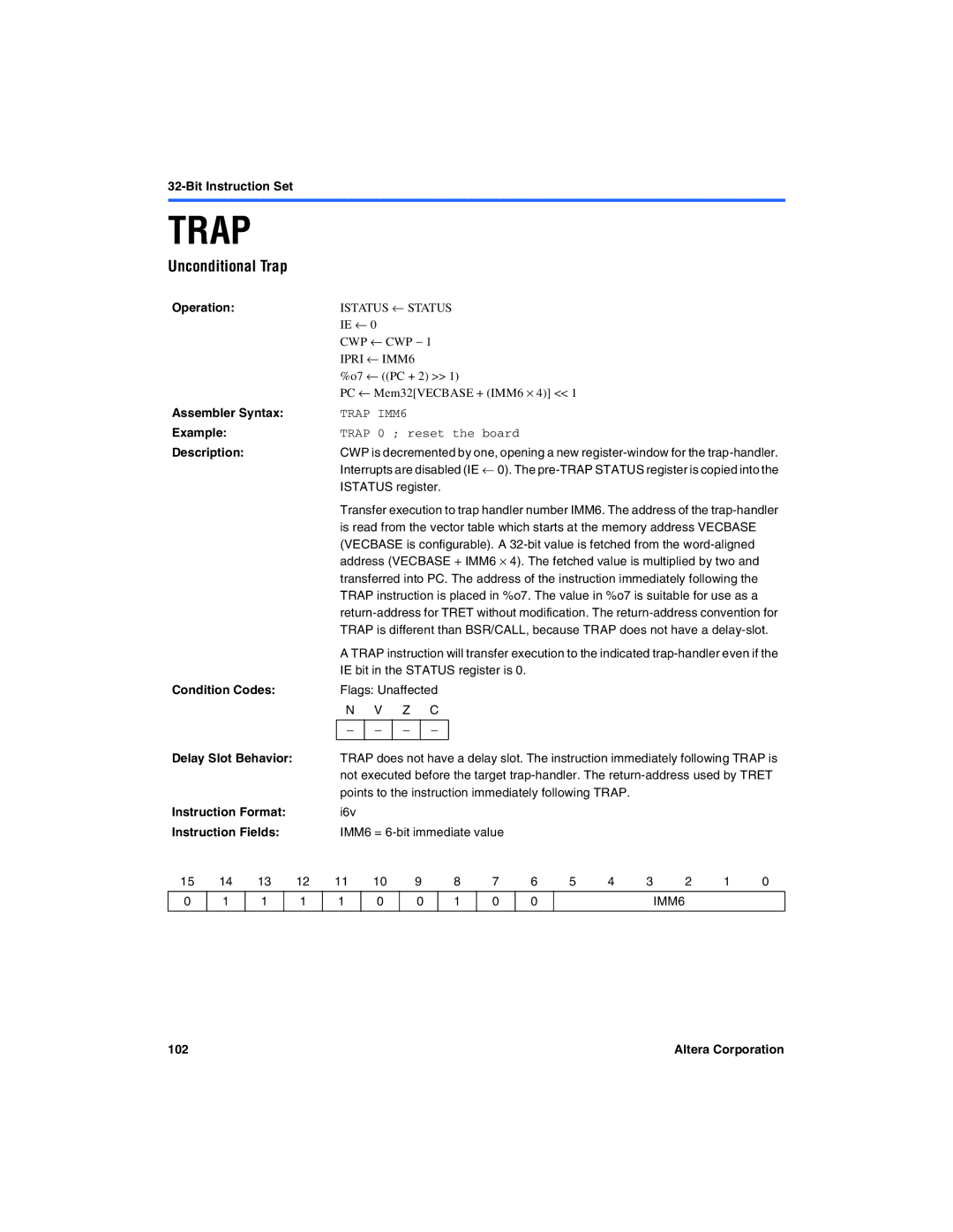
Trap
Unconditional Trap
Tret
Trap Return
Wrctl
Write Control Register
XOR
Bitwise Logical Exclusive or
XOR %rA,%rB
106
Index
Numerics
Index
Index
110