Example configuration with other FortiGate interfaces | FortiBridge operating principles |
1Connect the
2Connect the switch connected to the HA cluster external interface to the
3Connect the internal network to the
4Connect the
Connecting the FortiBridge-1000F (fiber gigabit ethernet)
The
1Connect the
2Connect the switch connected to the HA cluster external interface to the
3Connect the internal network to the
4Connect the
Example configuration with other FortiGate interfaces
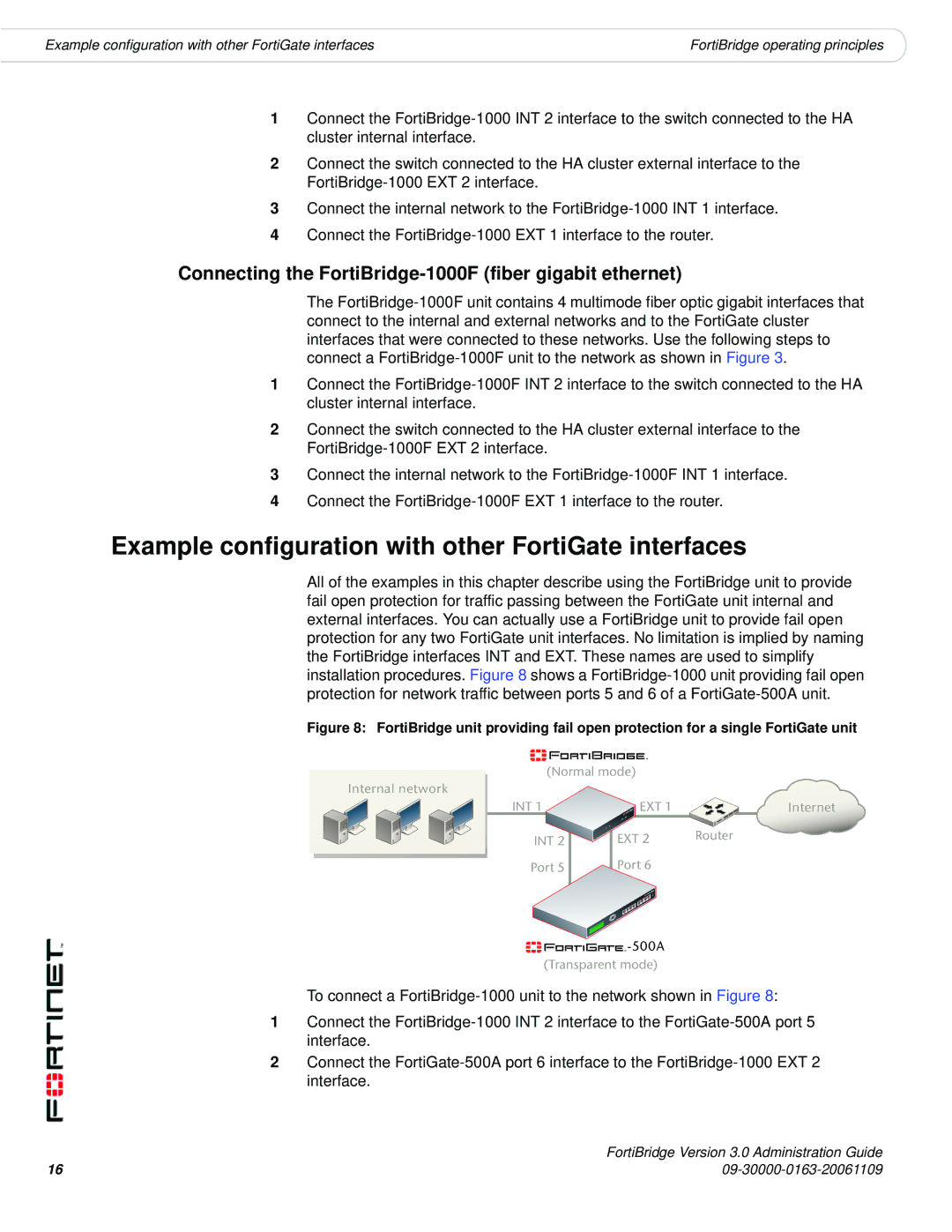
All of the examples in this chapter describe using the FortiBridge unit to provide fail open protection for traffic passing between the FortiGate unit internal and external interfaces. You can actually use a FortiBridge unit to provide fail open protection for any two FortiGate unit interfaces. No limitation is implied by naming the FortiBridge interfaces INT and EXT. These names are used to simplify installation procedures. Figure 8 shows a
Figure 8: FortiBridge unit providing fail open protection for a single FortiGate unit
(Normal mode)
Internal network
INT 1
INT 2
Port 5
EXT 1 | Internet |
EXT 2 | Router |
Port 6 |
|
![]()
![]()
![]()
![]()
![]()
![]()
![]()
![]()
![]()
![]()
![]()
![]()
(Transparent mode)
To connect a
1Connect the
2Connect the
16 | FortiBridge Version 3.0 Administration Guide |