Fortinet Version 3.0 manual Connecting and turning on the FortiBridge-1000F unit

Models: Version 3.0

1 88
Download 88 pages 53.91 Kb
Page 24
Image 24

Connecting and turning on the FortiBridge unit

Setting up FortiBridge units

To connect and turn on the FortiBridge-1000 unit

1Connect the FortiBridge-1000 INT 2 interface to the FortiGate unit internal interface.

2Connect the FortiBridge-1000 EXT 2 interface to the FortiGate unit external interface.

3Connect the FortiBridge-1000 INT 1 interface to the internal network.

4Connect the FortiBridge-1000 EXT 1 interface to the external network.

5Turn on the FortiGate unit and any network equipment that was turned off.

6Connect the AC adapter to the power connection at the back of the FortiBridge-1000 unit and to a power outlet.

The FortiBridge-1000 unit starts. The PWR and Bypass Mode LEDs turn on. After a short time, the FortiBridge unit switches to Normal mode. The Bypass LED goes out and the Normal LED turns on.

If the FortiGate unit and connected network components are turned on the FortiBridge-1000 INT 1, INT 2, EXT 1, and EXT 2 LEDs are also on.

Connecting and turning on the FortiBridge-1000F unit

Note: This procedure describes how to connect a
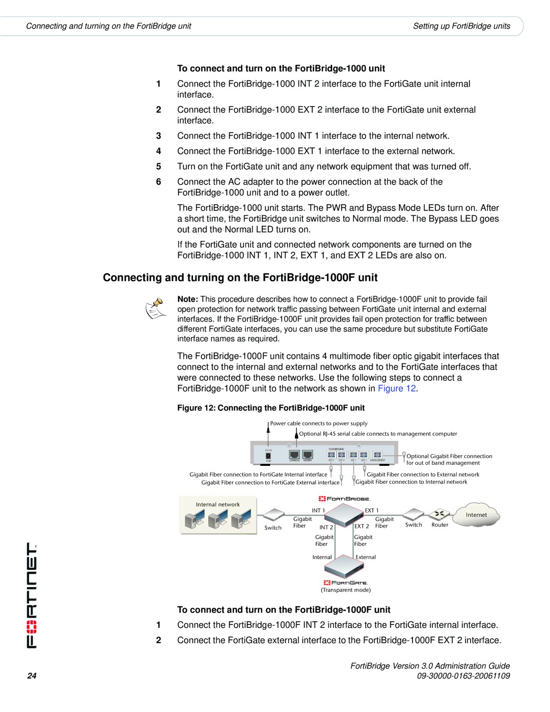
 FortiBridge-1000F unit to provide fail open protection for network traffic passing between FortiGate unit internal and external interfaces. If the FortiBridge-1000F unit provides fail open protection for traffic between different FortiGate interfaces, you can use the same procedure but substitute FortiGate interface names as required.

The FortiBridge-1000F unit contains 4 multimode fiber optic gigabit interfaces that connect to the internal and external networks and to the FortiGate interfaces that were connected to these networks. Use the following steps to connect a FortiBridge-1000F unit to the network as shown in Figure 12.

Figure 12: Connecting the FortiBridge-1000F unit

Power cable connects to power supply


Optional RJ-45 serial cable connects to management computer

DC+5V


TO FORTIGATE


PWR

CONSOLE MODEM

INT 2 EXT 2

INT 1

EXT 1

MANAGEMENT

Optional Gigabit Fiber connection

for out of band management


Gigabit Fiber connection to FortiGate Internal interface

Gigabit Fiber connection to External network

Gigabit Fiber connection to FortiGate External interface

Gigabit Fiber connection to Internal network

Internal network


INT 1

EXT 1


Internet


Gigabit


Gigabit


Switch

Router

Switch

Fiber

INT 2

EXT 2 Fiber


Gigabit

Gigabit


Fiber

Fiber


Internal

External

(Transparent mode)

To connect and turn on the FortiBridge-1000F unit

1Connect the FortiBridge-1000F INT 2 interface to the FortiGate internal interface.

2Connect the FortiGate external interface to the FortiBridge-1000F EXT 2 interface.

24

FortiBridge Version 3.0 Administration Guide

09-30000-0163-20061109

Page 24
Image 24
Fortinet Version 3.0 manual Connecting and turning on the FortiBridge-1000F unit