Model PD204
Safety Instructions
Important Safety Instructions
Table of contents
LCD display details
Recording/playback
Basic playback
Cue point setting
Advanced operations
Skip/locate functions
Menu mode
190
165
174
Specifications
Introduction of this manual
About replacing the lithium battery
Precautions on installation
Do not install the unit in the following conditions
Introduction Location Recorder Model PD204
Main features
Main features and functions
Time Code IN/OUT connectors
Mixer section
Options
Related products
Main features Location Recorder Model PD204
Preparation before using the PD204
Table of contents
Preparation of power supply
Mounting the battery
Important settings for using the battery
Low battery warning setting
Protector adjustment
Saving the battery power
Battery condition display
Dismounting the battery
Low battery warning setting
Using DC-IN Connecting the AC adaptor
Important settings for using DC
Turning on the power
Power switch
Press the ENTER/YES key to confirm the setting
Turning off the power
Use the Menu dial to adjust the display contrast
Display backlight and contrast
Internal clock setting
While SYS Setup is highlighted, press the ENTER/YES key
Use the Menu dial to select Edit and press the ENTER/YES key
Enter the desired date/time data
Slide the Open lever to the right
Preparation of a DVD-RAM disk
Inserting a disk
Insert a disk to the drive slot
Reel No
Initial format of a DVD-RAM disk
Drive
Format
Press the ENTER/YES key
While Are you sure? flashes, press the ENTER/YES key
While Reel No S001 is highlighted, press the ENTER/YES key
How to set the desired reel number
After formatting, press the Exit key to exit the Menu mode
Replacing the internal hard disk drive
Insert the optional hard disk drive to the slot
Cover the slot with the panel and fix it with four screws
Names and Functions
Left side panel inputs/outputs
Digital in connector XLR-3-31 tyep/balanced
Digital OUT connector XLR-3-32 tyep/balanced
USB Kybd connector Series a Receptacle/USB
Angle adjustment arm
USB Host connector Series a Receptacle/USB 2.0 High speed
USB PC connector Series B Receptacle
AUX in L, R connectors XLR-3-31 type/balanced
DC OUT connectors Hirose 4-pin, HR10A-7R-4S type/female
Adjust lever
Analog in 1 ~ 4 connectors XLR-3-31 type/balanced
Word in termination switch
Time Code OUT connector XLR-3-32 type/balanced
Time Code in connector XLR-3-31 type/balanced
WORD/VIDEO in and Word OUT connectors BNC type
About Non-shift mode and Shift mode
Power switch
Shift key/indicator
Front panel
Time / TC SET key
Example of a key with a SHIFTed function
Quick SET key
File SEL / DRV, PAT key
MENU/LINK Master dial / ENTER/YES key
Access indicator HDD, DVD
Exit / Batt key
Menu dial function
Clear key
PRE REC switch
JAM switch
14. / Prev and / Next keys
REC key/indicator red
Slate TONE, OFF, MIC switch
Pause key/indicator green
Circle Take / False Start key
Master L, R controls
When recording with the PRE REC mode set to on
Mixer section
Master Link key
LIM. indicator
Peak indicator
REV. indicator
Master LIM. indicator
Phones jack
ST BUS bargraph meters
LCD display
Monitor control
Input SEL switches
BATT1 indicator
BATT2 indicator
Disk tray
Stop key/indicator green
Microphone power supply switches
HPF switches
Play key/indicator green
Protectors
Battery mount
Rear panel
Time display
LCD display details
Home screen
Ubit ABS
Status information
Current drive/file number
File name/Next file name
Disk remaining
Protect icon
Screen examples
Menu list screen
Edit EDL File menu screen
Names and Functions Location Recorder Model PD204
Other connection
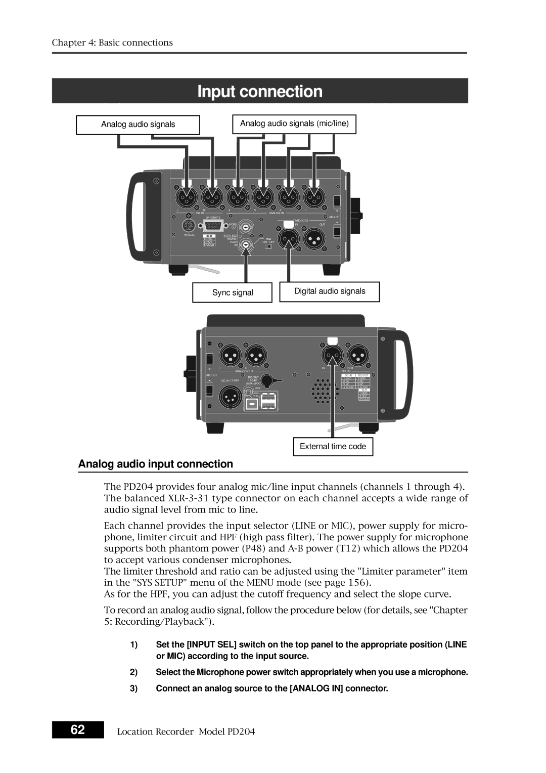
Input connection
Output connection
Input connection
Analog audio input connection
Digital audio input connection
Sync signal connection
External audio signal connection for monitoring
Time code input connection
Output connection
Analog audio devices Digital audio device
Time code output connection
Analog audio output connection
Digital audio output connection
Word clock output connection
Function keys
Other connections
USB keyboard connection
Other keys
Shortcuts
Control key
How it works
PC connection
External controller connection
Power connection
Optional AC adaptor, etc
Connection examples
Connection example for recording
For backup purpose
Basic connections Location Recorder Model PD204
Recording analog audio signals
Recording digital audio signals
Preparation before recording
Setup for recording in quick setup mode
How to make settings in the quick setup mode
Frame rate selection for LTC or external time code
System clock reference selection
Sampling frequency and bit length selection
TC generator mode setting TC recording mode
Clock pull up/pull down setting
Default file name setting
Settings in the Menu mode
Power source priority selection
Maximum file size setting
Mixer settings
Error tone output setting
Limiter setting
Input signal selection
High-pass filter setting
Adjusting the input gain for channels 1 through
Zero-crossing control function
About gain adjustment
Limiter function
Linking the Master L, R controls
Phase setting for channels 1 through
Controlling signals sent to the stereo bus
Monitoring recording signals
Monitor select dial Monitor control Phones jack
When the DVD drive is selected
Selecting the drive for recording
Slide the REC key
Recording analog audio
Starting recording
To stop recording, press the Pause key
Canceling recording False Start
About overloading during recording
Recording in Pre rec mode
Recording a slate tone/slate mic signal
Hints
Selecting the system clock
Recording digital audio
Selecting the sampling frequency/bit length
Selecting the TC frame rate
Selecting the TC generate mode TC recording mode
Recording time code
Off
Setting the time code output
Automatic record start by external time code
Repro
Set the JAM switch to on
Force jam to external time code
Viewing the cue point list
Cue point setting
Setting a cue point on the fly during audio recording
Editing a cue point
Editing a cue label
Adding a new cue point to the cue point list
Deleting a cue point
Selecting a file from the File SEL screen
Basic playback
Normal audio playback
Press the Play key to start playback
Cueing playback
Time code playback
To stop playback, press the Stop or Pause key
Skipping by cue point
Skip / locate functions
Skipping by file
Locating to the previous locate point
Locating to the beginning ABS 0 of a file
Locating to the end REC END of a file
After entering desired time value, press the Locate key
100
Locating to the desired time
101
Locating to the desired cue point
102
103
Selecting a partition
Back ground mode
104
Selecting auto copy mode
105
Making auto copy
Pressing the Exit key repeatedly to exit the Menu mode
106
Slide the REC key to start recording to the partition
107
Selecting source drive
While DVD is flashing, press the ENTER/YES key
108
Making disk copy
Rec area
109
If you are sure, press the ENTER/YES key
File copy function
110
111
Making file copy
112
When a recorded DVD-R or CD-R disk is set
When a recorded DVD-RW or CD-RW is set
After making audio file selection, press the ENTER/YES key
About mirror disk
Formatting in the DDR mode
113
114
Use the Menu dial to select DDR and press the ENTER/YES key
115
Making dual drive recording
Data export to PC
116
117
Connecting PC to the unit
How to unmount the PD204 from the PC
Example of exporting data to a computer application
118
Example of copying data to a computer hard disk
119
Click on Convert -, followed by Done indicated by an arrow
120
Creating and editing ALE files Edit EDL File menu
121
Creating a new ALE file
About an ALE file
123
While New file is highlighted, press the ENTER/YES key
After making necessary settings, press the Exit key
While Video format is highlighted, press the ENTER/YES key
While ALL-TAKE.ale is highlighted, press the ENTER/YES key
Adding audio file entries to an ALE file
125
While New entry is highlighted, press the ENTER/YES key
How to set a file as Circle Take
After adding audio file entries, press the Exit key
Viewing audio file entries
Viewing and editing audio file entries
127
Press the Exit key twice
Adding an audio file entry to an existing ALE file
Deleting an audio file entry
Press the ENTER/YES key to resave the ALE file
Editing an ALE file name
Editing an ALE file
129
After completing editing the name, press the ENTER/YES key
Select the desired type and press the ENTER/YES key
Remaking an ALE file
While Remake ALE is highlighted, press the ENTER/YES key
After Remake ALE completes, press the Exit key
131
Deleting an ALE file
Press the ENTER/YES key to delete the file
Page
Menu mode
133
About Menu mode
Menu name Contents Displayed order
135
SYS Setup menu
Characters you can enter using the Menu dial
Project name setting Set project name
Press the Exit key repeatedly until you exit the Menu mode
Characters you can enter using the alphanumeric keys
Take
Default file name setting Default file name
Date
Reel
139
After entering the scene name, press the ENTER/YES key
Default track name setting Default TrkName
Next event number setting Next event No
141
Recording FS/bit length setting Record FS&Bit
Pull up/down setting Pull up/down
143
Digital output signal format selection Digital out
Off Does not create a diagnoses file
Diagnoses file setting Diagnoses
145
Peak hold time setting Peak hold
Tone rec On/Off setting
Slate tone/pop tone recording mode setting Tone rec mode
Tone rec time setting
147
End pop tone setting
POP Tone
Pause cancel time setting Pause time
149
USB keyboard type setting Keyboard Sel
Pre recording time setting Pre rec time
151
Maximum file length setting Max file length
Continuous recording function Auto part. link
153
When Max file length is set to 4GB
Examples
False start mode setting False start
155
Delete
Threshold level setting
Limiter parameter setting Limiter parameter
Grouping setting
Mono The limiter for each channel works independently
Ratio setting
157
Analog OUT nominal level setting Stereo out level
Monitor speaker mute setting Speaker mute
159
Error tone output setting Error tone
Write error On or Off setting
161
Input clip On/Off setting
Batt warning On /Off setting
Disk warning time setting
AutoPly
Chain play mode setting Chain play
163
ROM version checking Version
165
Battery low voltage warning setting BATT. warning
While BATT. warning is highlighted, press the ENTER/YES key
DC-IN low voltage warning setting DC-IN warning
167
Power supply priority setting Power priority
Battery priority setting Active battery
169
Power priority BATT., Active battery BATT1
Battery setting examples
Power priority DC-IN, Active battery BATT1
171
BATT2
Battery remaining time BATT. Remain
Battery status BATT. status
173
174
Rec Run
While Sync Clock is highlighted, press the ENTER/YES key
System clock selection Sync clock
175
Video
TC frame rate selection Frame rate
176
Ext Run
Generator mode selection Gen mode
177
Free Run
Internal TC generator setting Set Gen TC
178
179
Editing the time code value in Rec run mode
Editing the time code value in Free run mode
180
User bit setting Set Gen Ubit
Jamming the time code value in Free run mode
181
Editing the user bit
Jam mode setting JAM mode
182
Repro
Time code output source selection Sel. TC Out
183
Gen
Press the ENTER/YES key again
Default LTC start time setting Default LTC start
184
LTC start time editing Edit LTC start
185
MMDDYYff
Ubit setting of playback time code RepTC Ubit
186
DDMMYYff
Off
Time code output while paused Rep pause TC
187
Automatic recording start by external TC Recin via ExtTC
188
Internal TC generator power-off timer TC PWR Timer
189
190
Enter the desired name
Editing a file name Edit file name
191
192
Line No Contents Details
193
Adding descriptor information
194
Editing descriptor information
Deleting descriptor information
Editing iXML Chunk data information
195
Viewing iXML Chunk data information
Select iXML descriptor and press the ENTER/YES key
Deleting an unnecessary audio file Delete file
196
Restoring a deleted audio file Restore Del. file
197
198
Format Mode
Formatting a disk or a hard disk partition Format
Drive
Make settings of the items
Volume label setting
Format mode selection
199
Normal
Physical format on/off setting
200
201
While Execute is highlighted, press the ENTER/YES key
Editing the reel number Volume label Reel No
202
Record protection On/Off setting Rec protect
203
Resume function On/Off setting Resume
204
Partition protection On/Off setting Part. protect
205
HDD operating time display HDD Ope. Time
206
Load Setup menu
207
User box selection
User box name entry
Specifications
209
Inputs/outputs
Analog Input CH1 ~
211
Recording/playback
General
Physical dimensions
Block diagram
Index
184
215
Declaration of EC Directive
Affect of Immunity on This Equipment
For the US Customers only
Fostex America Limited Warranty Shipping
Page
Fostex CO